Using Materials for Renderings

This task aims at showing you how to define the material attributes for a rendering.  

You can apply a material to each instance within a CATProduct. This functionality is especially relevant for rendering purposes since it lets you apply a different texture to each instance. Therefore, there will be as many materials as instances. The material preview will however display the last material applied to the instance.

For detailed information about applying a material and modifying material properties, refer to the Version 5 Real Time Rendering User`s Guide.

Open the Shooting.CATProduct document.

In case no material has been applied, the rendered image will be computed using the color and transparency defined in the basic graphic properties of the part, starting with the the object located at the lowest level in the specification tree. 
An object with no mapped material will appear as if it was made of matte plastic, without any relief and transparent or not (depending on the transparency degree defined in the Properties dialog box).

As a consequence, it is recommended to apply a material onto each part of your model in order to compute the image from the material properties and thus, generate a far more realistic image.

  1. In the specification tree, select the plus sign besides the item referred to as body.

  2. Right-click the Red Paint material then select Properties (or press Alt+Enter).

    The Properties dialog box is displayed:

    The various types of materials displayed in the drop-down list are explained below:
    • Default: This is the basic CATIA rendering (same as in the previous CATIA releases).
    • Architectural & Design: It includes all the parameters used by different shaders for tuning the material.
    • Diffuse: It is a simple diffuse material.
    • Polished Metal: It is highly reflective. The refection depends on the viewing angle (Fresnel effect) that is computed depending on the IOR in the range of 8-11. The reflection is not glossy.
    • Satinated Metal: It is highly reflective. The reflectivity depends on the viewing angle (Fresnel angle). The reflection is glossy
    • Brushed Metal: It is anisotropic and glossy.
    • Clear Glass: It is a fully physical model of glass. It includes reflectivity dependent on IOR (Fresnel effect), correct direction of refraction and total internal reflection.
    • Colored Glass: It is a fully physical model of glass. It includes reflectivity dependent on IOR (Fresnel effect), correct direction of refraction and total internal reflection. Glass color depends on the thickness of the object. The shader allows to specify a target color for a given distance (such as a color at 10mm thickness).
    • Frosted Glass: It is a fully physical model of glass. It includes reflectivity dependent on IOR (Fresnel effect), correct direction of refraction and total internal reflection. In addition, it has glossy refraction.
    • Polished Plastic: It is mostly diffuse with a smaller non glossy reflection. The reflection depends on the viewing angle.
    • Soft Plastic: It is mostly diffuse with a glossy reflection. The reflection depends on the viewing angle.
    • Simple Translucent: It uses a single color for front, medium and backside. This is the effect that is easiest to understand and control for standard users.
    • Backside Translucent: It allows to set color of backside.
    • Reflective Translucent: It is used for translucent materials with a reflective front side. It also has glossy reflection.
    • Metallic Paint: The paint is reflective with no flakes. The reflectivity depends on the viewing angle. The reflection is non glossy.
    • Car Paint: Car paint is reflective with flake. The reflectivity depends on the viewing angle. The reflection is non glossy.
  3. Select the Colored Glass type. The Properties dialog box is as shown as below:
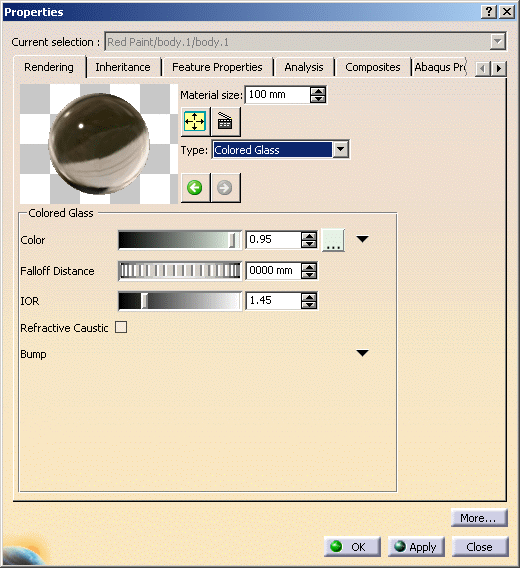
    • Clicking the downward arrow sign besides a parameter displays Connect Parameter dialog box listing shaders that can be connected(new instances and pre-existing ones).

      The allowed new instances vary depending on the parameter type:

      • Scalar parameter: Scalar Texture
      • Color parameter: Color Texture
      • Bump parameter: Bump Texture, Round Corners
    • Right-clicking the arrow sign besides a parameter displays the following options:
      • Connect: Displays the Connect Parameter dialog box.
      • Disconnect: Disconnects from the already connected parameters.
      • Edit: Allows you to edit the parameters.
    • Selecting a shader in the Connect Parameter dialog box replaces the existing parameters with new ones.
      • Scalar Texture allows to map a texture and use its color intensity as a varying scalar.
      • Color Texture allows to map a texture and use its varying color.
      • Bump Texture allows to map a texture that creates a bump effect depending on the variations of texture color intensity.
      • Round Corners creates an effect of rounded edges. It provides shading effect to straight edges.


    • The navigation buttons allow you to return to the parent shader or go forward to the child shader.
       
  4. Now select the Default material type, and click the Rendering tab to define the Lighting parameters:

    Ambient: the intensity of light diffused in any direction by the object, even if not lit by any light source. The ambient light is essentially used to show objects or parts of objects that are not illuminated directly by the light source.
    The intensity is defined by a coefficient (with a value between 0 and 1). 
    This parameter affects the whole object, including the shadowed area.

    Diffuse: the intensity of light diffused by the object when lit by light sources. The intensity is defined by a coefficient (with a value between 0 and 1).
    Typically, a shiny metal surface would have a diffuse reflectance value close to 0, while a piece of cardboard would have a value probably above 0.9.

    Specular: intensity and color of light reflected in one particular direction (highlights).
    Typically, a polished object would have a high value for the specular reflectance coefficient, while a more mat surface would have a lower one.

    Roughness: dullness of an object (size of the reflecting zone). 
    Set the value to a minimum to generate very sharp highlights on very shiny surfaces. Set the shininess to a higher value to generate large specular spots creating a duller effect on rougher surfaces.

    Transparency: the degree of transparency of an object and color of the filter interfering with the light passing through an object.
    The transparency color acts like a photographic filter which modifies artificially the light rays received by an optical lens.
    It is generally identical to the ambient and diffuse color but when it is different, the shadows cast by the object are colored accordingly. For instance, a blue object with a red transparency color will cast slightly red shadows.
    The higher the value, the more transparent the object (in the example the value is 0.75), the lower the value, the more opaque the object.

    Refraction: degree of light passing obliquely through an object. The refraction is defined by a coefficient (value between 1 and 2).
    Set to 1, the transparent object will show no light distortion. As an example, water has a 1.2 coefficient.

    Reflectivity: degree of reflectivity of an object. Set to a high value, the object reflects its environment.

  5. Click the Texture tab to edit the material texture parameters.

    You can select the Flip U, V check boxes to invert the material texture along U and V axes.

    Note that when clicking the ... button to open the File Selection dialog box and choose a new texture, an additional dialog box might appear simultaneously depending on the document environments (i.e. the method to be used to access your documents) you allowed in the Document tab. This additional window lets you access your documents using an alternate method and looks something like this:
    In our example, four document environments have been allowed among which the DLName environment. If you want to access your texture files using DLNames, for instance, click Logical File System: this opens a specific dialog box dedicated to the DLName environment.
    For detailed information on the Browse dialog box, refer to Opening Existing Documents Using the Browse Window.

    For more information on this tab, refer to the Version 5 Real Time Rendering User's Guide - Modifying Material Texture Properties.

    A preview is displayed in the Properties dialog box but it slightly differs from the rendered image. The following are examples of rendered images with their corresponding lighting preview:
    Lighting Preview Quick Render
    Default

    Transparency = 0.90

    Reflectivity = 0.94

    In order to get a more precise idea of the rendered material appearance, you can click the Ray Traced Preview button to display a preview of the material in the Properties dialog box. To deactivate this preview mode, click the button once again.

  6. Click OK.
    The material attributes are defined.