 |
This task shows how to insert a
Circular Milling operation in the program. To create the operation you must
define:
- the tool that will be used

|
 |
Open the
HoleMakingOperations.CATPart
document, then select the desired Machining workbench from
the Start menu.
Make the Manufacturing Program current in the specification tree.
|
 |
1. |
Select
Circular Milling
 . .
A Circular Milling entity along with a default tool is added to the program.
The Circular Milling dialog box appears directly at the
Geometry tab page
 . .
|
 |
|
2. |
If needed, enter
Offset values for the Bottom and Contour. |
|
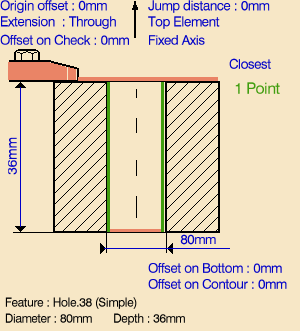
3. |
Select the red hole
depth representation then select hole geometry in the 3D window.
Just double click to end your selections. |
|
4. |
If needed,
you can invert the tool axis direction by selecting the axis representation
in the sensitive icon. |
|
5. |
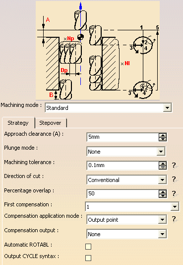
Select the Strategy tab page
 and choose the machining mode:
|
 |
|
6. |
Specify the
machining strategy parameters,
which are common to the two machining modes:
- Compensation number depending on those available on the tool
- Compensation application mode
- Compensation output, which allows
you to manage the generation of Cutter compensation (CUTCOM) instructions
in the NC data output.
|
|
|
Stepover parameters for
Standard machining mode:
- Number of paths and Distance between paths
- Spring pass
- Axial mode: Maximum depth of cut or Number of levels (with or without
top)
- Sequencing mode: Axial first or Radial first
|
|
|
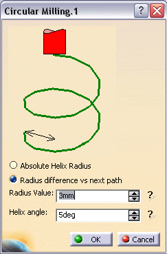
Stepover parameters for
Helical machining mode:
- Breakthrough
- Number of paths and Distance between paths
- Spring pass
- Helix mode: By angle or By pitch
|
|
7. |
A tool is proposed
by default when you want to create a machining operation. If the proposed
tool is not suitable, just select the Tool tab page
 to specify the tool you want to use. This is described in
Edit the Tool of an Operation.
to specify the tool you want to use. This is described in
Edit the Tool of an Operation.
For Circular Milling you can use one of
the following:
- End Mill
- Face Mill
- Conical Mill
- Drill
- Spot Drill
- Countersink
- T-slotter.
|
|
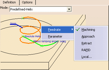
8. |
Select the
Feeds and Speeds tab page
 to specify the feedrates and spindle speeds for the operation.
Note that in the toolpath represented in the strategy page, tool motion
is at:
- Motion at machining feedrate from 1 to 2
- Motion at feedrates defined on macros from 2 to 3, 3 to 4, 4 to
2', 2' to 3' and 3' to 4'
- Retract at retract feedrate from 4' to 5.
|
|
9. |
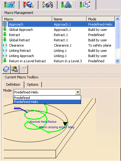
Select the
Macros tab page
 to specify the operation's transition paths (approach and retract motion,
for example). The general procedure for this is described in
Define Macros of an Axial Machining Operation.
to specify the operation's transition paths (approach and retract motion,
for example). The general procedure for this is described in
Define Macros of an Axial Machining Operation. |
| |
10. |
|
| |
|
|
| |
|
|
|
|
|
|
 |
|
Before accepting
the operation, you should check its validity by
replaying the tool path. |
|
11. |
Click OK to create
the operation. |
|
|
|
Example of output
If your PP table is customized with the following statement for Circular
Milling operations:
		CYCLE/CIRCULARMILLING, %MFG_TOTAL_DEPTH, %MFG_FEED_MACH_VALUE,
		&MFG_FEED_UNIT, %MFG_CLEAR_TIP
A typical NC data output is as follows:
		CYCLE/CIRCULARMILLING, 38.500000, 500.000000,
		MMPM, 2.500000
You can use Edit Cycle
 to edit or choose output syntaxes. For more information please refer to
Editing Cycle Syntaxes in Axial
Machining Operations.
to edit or choose output syntaxes. For more information please refer to
Editing Cycle Syntaxes in Axial
Machining Operations.
The parameters available for PP word syntaxes for this type of operation
are described in the
NC_CIRCULAR_MILLING section of the Manufacturing Infrastructure User's Guide.
|
|

|
