-
Click Edge Fillet
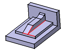
 and fillet the four edges as shown using 5mm as the radius value.
Careful! When you select edges, the order of selection affects the final shape of the fillet. This explains why you may sometimes encounter error messages when filleting.
To obtain the shape we need for our scenario, select the edges counter-clockwise.
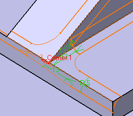
Take a closer look at the resulting corner: the shape style is not satisfactory.

-
To round the corner again, double-click the fillet and in the dialog box click the More button to access additional options.
-
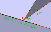
Right-click the Blend corner(s) field and select Create by edges. In our example, only one corner is detected. The application shows it in the geometry area (3D text).

-
The setback distance determines for each edge a free area measured from the vertex along the edge. In this area, the system adds material so as to improve the corner shape.

The Blend Corner option is available through the
Variable Radius Fillet command
![]() too.
too.
-
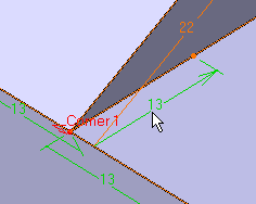
Enter a value in the setback distance field. For example, 13.
-
Click Preview to examine the result.
To edit the distance for the top edge, click 13 and enter 22 as the new value in the Setback distance field. -
Repeat the operation for the edge below (see arrow) using the same distance value, 22.

-
Click OK to confirm the operation.
The corner is reshaped.
More About Blend Corners
When editing an edge fillet containing at least one blend corner, the following options are available in the Blend corner(s) contextual menu.
|
When no corner is created, only the Create by edges and Create by vertex commands are displayed in the contextual menu.