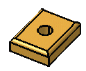
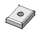
This task shows you how to translate a body. The Translate command applies to current bodies.
To perform this task, open the CATPart of your choice.
-
Click Translation
 in Transformation Features toolbar (Transformations
sub-toolbar).
A message appears asking you about the result you wish to obtain:-
You can decide to keep the new specifications induced by the operation: in this case, just click Yes to go on using the command you have just selected.
OR
-
You can decide not to keep the new specifications: in this case, click No to cancel the command you have just launched.
-
For Generative Sheetmetal Design workbench, Click
Translation
![]() in Transformations toolbar (Isometrics
sub-toolbar).
in Transformations toolbar (Isometrics
sub-toolbar).
-
Click Yes.
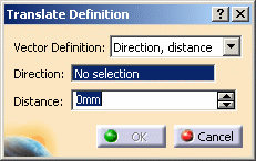
The Translate Definition dialog box appears.

-
Select a line to take its orientation as the translation direction or a plane to take its normal as the translation direction. For example, select zx plane.
You can also specify the direction by means of X, Y, Z vector components by using the contextual menu in the Direction field. -
Specify the translation distance by entering a value or using the drag manipulator. For example, enter 100mm.
-
Click OK to create the translated element.
The element (identified as Translate.xxx) is added to the specification tree.