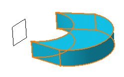
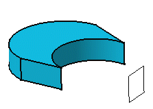
To perform this task in the Generative Sheetmetal Design workbench, open the CATPart of your choice.
-
Click Symmetry
 in Transformation Features toolbar (Transformations
sub-toolbar).
in Transformation Features toolbar (Transformations
sub-toolbar).A message appears asking you about the result you wish to obtain:
- You can decide to keep the new specifications induced by the operation: in this case, just click Yes to go on using the command you have just selected.
OR
- You can decide not to keep the new specifications: in this case, click No to cancel the command you have just launched.
-
Click Yes.
The Symmetry Definition dialog box appears.

-
Select a point, line or plane as reference element. For the purpose of our scenario, select zx plane .
-
Click OK to create the symmetrical element.
The original element is no longer visible but remains in the specification tree. The new element (identified as Symmetry.xxx) is added to the specification tree.
