This task shows
you how to create
a wall by extrusion.
You can extrude sketches composed of lines, circles, projection of lines,
and projection of circles. You can also extrude all kinds of opened
profiles.
You must have defined the Sheet Metal parameters.
Open
NEWExtrude1.CATPart document.
-
Click Extrusion
 in the
Walls
toolbar.
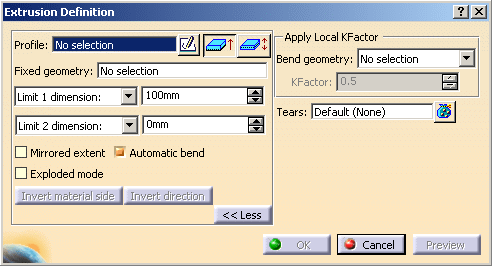
The Extrusion Definition
dialog box is displayed.
-
Select a sketch.
Several types of extrusions are available for both Limit 1 and Limit 2: - Dimension: The requested input data are a sketch and a dimension,
- Up to plane or Up to surface: A plane or a surface is the input as a limit to the extrusion. These functions are used to create walls that are not rectangular.
-
Edit the Limit 1 dimension: and Limit 2 dimension: to set both extremities to a desired value.

By default, the Limit 1 dimension: value is positive. 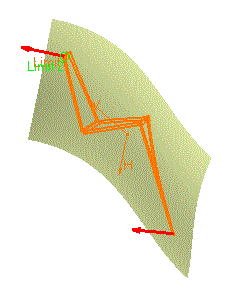
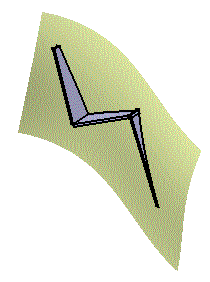
The sketch you selected appears in the Profile field.
You can now edit it by clicking the Sketch icon if you want to modify
it.
The Sketch at extreme position is active by
default. You can
set its position to middle by clicking Sketch at middle
position
 .
. -
Define the options as needed:
-
Select the option Mirrored extent to extent the material on both sides of the sketch. In this case, only Limit 1 dimension: can be edited.
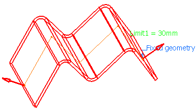

This option is only available if the type is set to Dimension.
-
Click Invert material side button to invert the direction of the creation of the material.
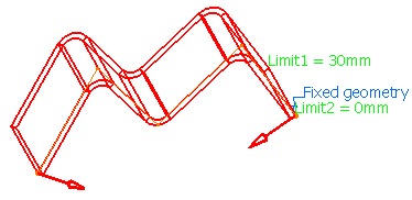
-
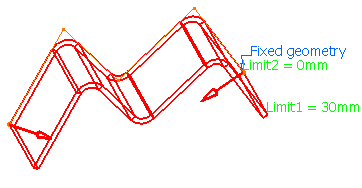
-
Click OK.
The extrusions corresponding to the selected sketch are created according to the specified options, and are added to the specification tree.
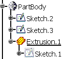
- When the extrusion is the first sheet metal feature of the Part, the reference wall is the first wall created based on the first segment of the sketch.
- For the option Up to Surface, while the wall end that is
limited by the surface has the shape of the surface, its thickness
does not fit the surface. It is a rectangular polygon defined by
the first edge that comes into contact with the surface.

- Extrusion walls can be edited.
Exploded Mode
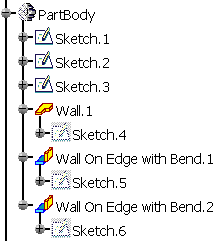
You can select the option Exploded
mode before clicking OK.
Creating an extrusion
can be just an acceleration of the design but very often it is just an
intermediate state. It is recommended to explode the extrusion into
several elementary features (wall,
sketch based wall on edge,
bend, sub extrusion (extrusion with a sub profile of the
initial profile) etc.) to enable modifications.
-
If the extrusion is not connected to the sheet metal part and therefore is not linked to a support, the first feature can either be:
-
A wall (If fixed geometry is at profile extremity and on the line)
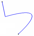
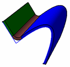
Initial configuration
(3 lines, 1 curve)Exploded Mode
(1 wall, 1 bend and 1 sub extrusion)- A sub extrusion (If fixed geometry is at profile extremity and on the curve)

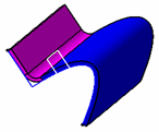
Initial configuration
(3 lines, 1 curve)Exploded Mode
(1 sub extrusion and 1 wall on edge) -
- If the extrusion is connected to the sheet metal
part and therefore is linked to a support, the first feature can either be:
- A tangent wall on edge (if the connected part of sketch is line)


Initial configuration
(1 line and 1 curve)Exploded Mode
(1 tangent wall on edge and 1 sub extrusion)- A sub-extrusion (if the connected part of sketch is curve)

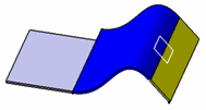
Initial configuration
(1 curve and 1 line)Exploded Mode
(1 sub extrusion and 1 tangent wall on edge)- A wall on edge (if the connected part of sketch is line followed by sharp vertex (or circular curve) and line)
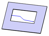
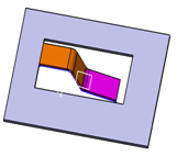
Initial configuration
(3 lines)Exploded Mode
(1 extrapolated wall on edge with bend and 1 wall on edge with bend)- A wall on edge (if the connected part of sketch is circular curve followed by line and extrusion is created with limit types as dimension)
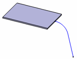
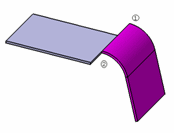
Initial configuration
(1 circular curve and 1 line)Exploded Mode
(1 wall on edge with bend)In such configurations, bends generated have one or both extremities as closed shape type.
- A sub-extrusion (if the connected part of sketch is circular curve followed by line and extrusion is created with limit types as up to plane or up to surface)
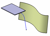
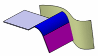
Initial configuration
(1 circular curve and 1 line)Exploded Mode
(1 sub extrusion and 1 tangent wall on edge)
- If a limit is specified for extrusion (up to plane or up to surface), the bends (including bend in wall on edge) generated has both extremities as curved shape type. This is applicable when the extrusion is not connected to the sheet metal part.
-
After the explode, there is no more links to the original sketch. Any change in the sketch will have no impact on the exploded features.
-
The sketches generated for walls and sub extrusions are under-constrained. The sketches generated for the wall on edge are fully-constrained.
-
In case of explode of extrusion created with Sketch at extreme position option, all the generated sketches are located at the extrusion profile. While in case of explode of extrusion created with Sketch at middle position option, wall and wall on edge sketches are located at either side of extrusion profile with offset of sheet metal thickness/2 and sub-extrusion profiles are located at extrusion profile.
Fixed Area
The fixed area is specified through a border vertex or an edge of the profile. CATIA proposes a default fixed geometry, but you can change it in the Fixed geometry field.
Automatic Bend
This
option allows you to make fillets on sharp vertices of the profile. This
option is activated by default.

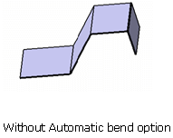
Degeneration of Curve Elements
There can be a degeneration of curve element. There are following two cases:
|
If there is a degeneration of a curve element for extrusion profile, an error is displayed.
KFactor Management
You can specify the KFactor for a bend generated from the extrusion of a circle contained in the sketch as well as for a bend automatically computed. To specify a KFactor, select geometry in the sketch that will lead to the creation of a cylindrical face. For a bend automatically computed you have to select the sharp vertex common to the two edges that will generate the fillet.
All the vertices or edges chosen for a specific KFactor value are added in the Bend geometry field. If there are several elements in the Bend geometry field, selecting the text symbol in the 3D will automatically update the Bend geometry field with the appropriate geometry.
For all the other bends if no specification is given the KFactor applied will follow the rule defined in the Sheet metal parameters (DIN if not deactivated) or will follow the bend table (if set in the Sheet metal thickness table).
|
|
If the extrusion contains non-canonical edges (other geometry than lines or circles) the KFactor applied to the resulting face will always be 0.5. |
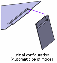
Automatic Connection to the Sheet Metal Part
The Extrusion automatically connects to the sheet metal part and several
volumes of the part together. There is no specific option to do this.
The extrusion is connected when its lateral faces can be merged
with a lateral face of the sheet metal part. If an area of the
extrusion is overlapping the sheet metal part it is not connected. If
the extrusion has not been connected a warning message is displayed showing
no union has been done for that particular extrusion.
If the extrusion is connected to the sheet metal parts, the
selection of a fixed geometry has no effect.
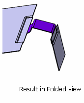
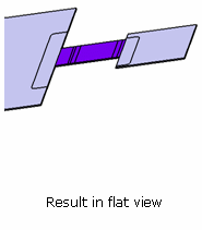
Tears Selection
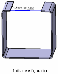
Tears allow you to control the union of the extrusion with the
sheet metal part.
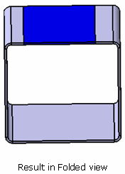
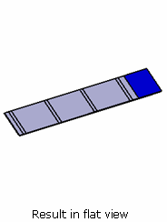
The profile and the resulting extrusion are colored in blue and
you can see that you need to tear the sheet metal part to unfold it. The
left edge has been selected as a tear face.
The closed, intersecting or multi-domain sketch is not allowed for extrusion creation.
![]()