These steps apply to Structure Functional Design, Ship Structure Detail Design, and Structure Design applications.
A built-in end cut is created by subtracting a volume from a profile (shape/stiffener). This volume is modeled using a set of parameters. The administrator defines these parameters and assigns a name to the end cut. The advantage of using a built-in end cut is that the data size of the model is smaller.
Built-in End Cut Parameters
Flange Parameters
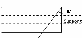
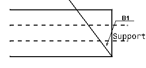

B3O1 is the location of B3 as distance from face WebInner+.
B3O2 is the location of B3 as distance from face WebInner-.
To define the point of incidence for B3, you must assign a value to either B3O1 or B3O2. This is true even if the offset value is 0.

B4O1 is the location of B4 as distance from face WebInner+.
B4O2 is the location of B4 as distance from face WebInner-.
To define the point of incidence for B4, you must assign a value to either B4O1 or B4O2. This is true even if the offset value is 0.
Web Parameters
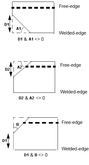
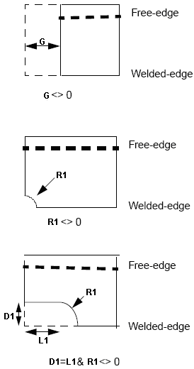
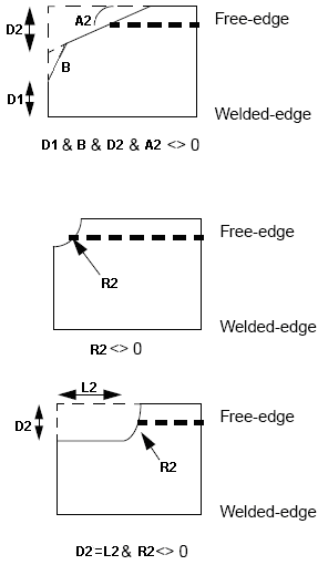
Most combinations of these parameters can be used to create built-in end cuts. However, usage of certain combinations is restricted as these result in conflicting geometry. For example,
- R1 with A1
- R2 with A2
Creating a Built-in End Cut

.../OS/startup/EquipmentAndSystems/Structure/DetailingFeatures
For more information, see Design Tables in Infrastructure User's Guide.
Enter the end cut name (PartNumber) and values for the required parameters. In the given example, appropriate parameter value is assigned to create a Web-Snipe-Radius-R1 end cut.

.../OS/startup/EquipmentAndSystems/Structure/DetailingFeatures
Add this CATPart to the catalog. For more information about adding a CATPart to a catalog, see Adding Slots, End Cuts and Small Assemblies Templates to a Catalog.
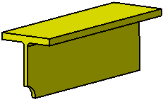
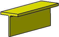
The image below shows the Web-Snipe-Radius-R1 end cut placed on a stiffener. For more information about placing end cuts, see Placing End Cuts.
| Before placing end cut | After placing end cut |
 |
 |
![]()