 |
This task shows how to generate a mesh model from a Structure Design
model. |
 |
1. |
Load an existing Structure
Design model, and prepare the analysis document. |
| |
2. |
Create a new CATPart. In this
example, its name is Proxy_1. |
| |
3. |
Create an Analysis
document associated with this proxy CATPart by switching to the
Advanced Meshing Tools workbench in Analysis Simulation.
Now save the Analysis document. For a more detailed
explanation, see Analysis User Guide. |
| |
|
 |
| |
4. |
Insert this Analysis document
into the product containing the design model.
(To do this, select the
product and then select Insert - Exiting Component
from the menu bar.)
NOTE: Make sure the loaded Analysis document
is empty and is not associated with other design models. You can check
if the Proxy CATPart is populated from the previous execution of the
command. If it is, repeat this step and load an empty Analysis document. |
| |
|
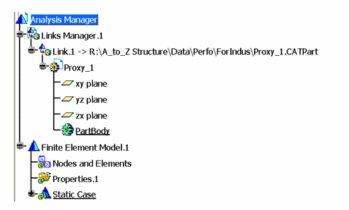
Specification tree now looks like this:

|
| |
5. |
Start the Structure
Functional System Design workbench.
Click the Create Mesh button
 on the Structural Systems toolbar.
NOTE: To use the Create Mesh command, you need a license
for Generative Assembly Structural Analysis (GAS) and Finite
Element Model Surface (FMS).
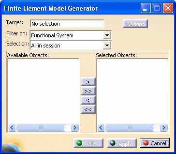
The Finite Element Model Generator dialog box displays.
 |
| |
6. |
Select the Finite Element Model
from the specifications tree. In this example, Finite Element
Model.1 displays in the Target field. |
| |
7. |
Select Functional System
from the Filter On drop down list. |
| |
8. |
Select All in session
from the Selection drop down list to add every Super Object
the Available Objects list.
You can then select the appropriate objects from the Available
Objects list, and push them to the Selected Objects
list. NOTE: You can also select the appropriate objects in your 3-D
session, or from the specifications tree. |
| |
9. |
Select the Options
button.

|
| |
|
FEM Options
|
| |
|
Surface 2D Mesh
|
| |
|
Beam 1D Mesh
|
| |
|
Misc. Options
|
 |
|
|
| |
10. |
Click OK. The mesh
generation may take several minutes, depending on the model size and the
performance of your computer. |
|
11. |
Switch to the Analysis
workbench. |


![]() on the Structural Systems toolbar.
on the Structural Systems toolbar.
