
|
This task shows how to create a swept surface
that uses an explicit profile. |
|
You can create a swept surface by sweeping out a profile in
planes normal to a spine curve while taking other user-defined parameters
(such as guide curves and reference elements) into account.
You can sweep an explicit profile:
- along one or two guide curves (in this case the first guide curve is
used as the spine)
- along one or two guide curves while respecting a spine.
|
| |
|
| |
The following sub-types are available:
|
 |
Open the
Sweep1.CATPart document. |
| |
With reference surface
|
 |
-
Click Sweep
 . .
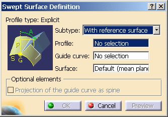
| The Swept Surface Definition dialog box appears. |
-
Click the Explicit profile icon, then select
With reference surface from the drop-down list.
-
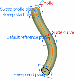
Select the planar
profile to be swept out, that is the circle.
-
Select a guide
curve (DemoGuide1).
-
Click OK to create the swept surface.
| The surface (identified as Sweep.xxx) is added to the
specification tree. |
| |
 |
Check
Projection of the guide curve as spine so that the projected
spine is the projection of the guide curve onto the reference plane.
It is available with the Reference surface sub-type if the
reference surface is a plane. |
|
| |
With two guide curves
|
 |
-
Click Sweep
 . .
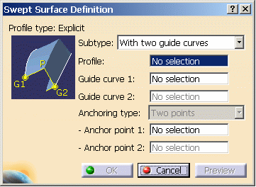
| The Swept Surface Definition dialog box appears. |
-
Click the Explicit profile icon, then select
With two guide curves from the drop-down list.
-
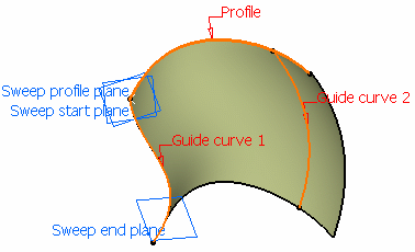
Select the
Profile to be swept out (DemoProfile2).
-
Select Guide curve
1 (DemoGuide1).
-
Select Guide curve
2 (DemoGuide2).
 |
| You can also specify anchor points
for each guide. These anchor points are intersection points between
the guides and the profile's plane or the profile itself, through
which the guiding curves will pass.
You can define the following anchoring
type: Two points. Select an anchor point on each guide curve. If the
profile is open, these points are optional and the extremities of the
profile are used. |
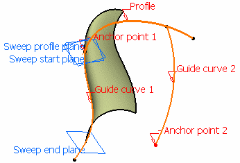 |
If you do not explicitly select anchor
points or anchor direction, they are automatically computed if the
profile is planar. Note that the selection is still available. The
anchor points are computed as follows:
- for Anchor point 1: intersection between the profile plane and
Guide curve 1 (I1).
- for Anchor point 2: intersection between the plane, passing
through Anchor point 1 and normal to the spine, with
Guide curve 2 (I2).
|
-
Click OK
to create the swept surface.
| The surface (identified as Sweep.xxx) is added to the
specification tree. |
| |
 |
Check
Projection of the guide curve as spine so that the projected
spine is the projection of the guide curve onto the reference plane. |
|
| |
With pulling direction
|
| |
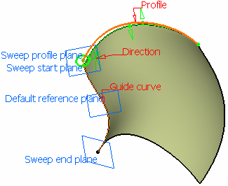
The With pulling direction subtype is equivalent to the
With reference surface subtype with a reference plane normal to the pulling
direction. |
 |
-
Click Sweep
 . .
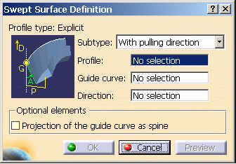
| The Swept Surface Definition dialog box appears. |
-
Click the Explicit profile icon, then select
With pulling direction from the drop-down list.
-
Select the
Profile to be swept out (DemoProfile2).
-
Select the Guide curve (DemoGuide2).
-
Select a
Direction (zx plane).
-
Click OK to create the swept surface.
| The surface (identified as Sweep.xxx) is added to the
specification tree. |
| |
 |
Check
Projection of the guide curve as spine so that the projected
spine is the projection of the guide curve onto the reference plane. |
|
|

|
 .
.
 .
.
 .
.
![]()

