Masses
You can add mass to a model to make it match a known value, such as the mass of the actual assembly. Adding mass can account for nonstructural features or other details that are not included in the model but whose mass may affect the analysis results. Masses are added in a Masses objects set. The following mass tools are available in Nonlinear Structural Analysis for structural analysis:
 Creating Mass Sets: Creates the Masses
objects set required before you can add mass objects to
the analysis case.
Creating Mass Sets: Creates the Masses
objects set required before you can add mass objects to
the analysis case.
 Creating Distributed Masses: Applies a
distributed mass to a geometry selection. This tool is
also used to define point masses.
Creating Distributed Masses: Applies a
distributed mass to a geometry selection. This tool is
also used to define point masses.
 Creating Line Mass Densities: Applies a
mass per unit length to a geometry selection.
Creating Line Mass Densities: Applies a
mass per unit length to a geometry selection.
 Creating Surface Mass Densities: Applies a
mass per unit area to a geometry selection.
Creating Surface Mass Densities: Applies a
mass per unit area to a geometry selection.
 Creating Distributed Masses and
Inertias: Applies a distributed mass and
inertia to a virtual part.
Creating Distributed Masses and
Inertias: Applies a distributed mass and
inertia to a virtual part.
Nonlinear Structural Analysis uses the same mass tools that are available in the Generative Structural Analysis workbench. In some cases GPS allows the use of supports that are not useful in a nonlinear structural analysis. If you select a support that the solver cannot use, it will generate an error message when the input file is written. Table 9–4 summarizes the supports to which each type of mass can be applied for a nonlinear structural analysis.
Table 9–4 Supports for masses.
| Mass | Point, Vertex, or Point Group | Curve, Edge, or Line Group | Surface, Face, or Surface Group | Virtual Part |
|---|---|---|---|---|
| Distributed Mass | ||||
| Line Mass Density | ||||
| Surface Mass Density | ||||
| Distributed Mass and Inertia |
Creating Mass Sets
Before you can create nonstructural masses on a model, you must create a Masses object set to hold them.
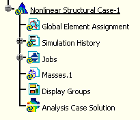
To create a new mass set, click in the Masses toolbar. The
Masses object set appears in the specification tree
under the current analysis case.
 Creating Distributed
Masses
Creating Distributed
Masses
Distributed masses are distributed over the selected geometry. The number and type of supports determine how the mass is applied to the model. For example, a distributed mass applied to several edges is divided into mass per unit length and applied evenly along the edges, whereas a distributed mass applied to surfaces is divided into mass per unit area. Distributed masses can also be used as supports for gravity loads.
Distributed masses can be applied to points, vertices, curves, edges, surfaces, or faces or to point, line, or surface groups. However, all supports for a single distributed mass must be of the same type.
Since distributed masses can be applied to a point, vertex, or point group, they are also used to create point masses. Point masses apply a mass to a single point or distribute it over the points in a group. You create point masses in the same way as you create other distributed masses.
![]() This task shows you how to create a
distributed mass on geometry.
This task shows you how to create a
distributed mass on geometry.
-
Click the Distributed Mass icon
.The Distributed Mass dialog box appears, and a Distributed Mass object appears in the specification tree under the Masses objects set for the current analysis case.
-
You can change the identifier of the mass by editing the Name field.
-
Select the geometry support (points, edges, or faces). Any selectable geometry is highlighted when you pass the cursor over it. You can also select a point group. You can select several supports to distribute the mass over all supports simultaneously, but all supports for a single distributed mass must be of the same type—for example, you cannot select vertices and edges as supports for the same distributed mass.
Note: Edge supports should be used only for beam geometry, and face supports should be used only for shell geometry.
The Supports field is updated to reflect your selection.
-
Enter the mass in the Mass field.
Nonlinear Structural Analysis uses the entered mass value directly for point supports or converts it to mass per unit length or mass per unit area for edge supports and face supports, respectively.
-
Click OK in the Distributed Mass dialog box.
Symbols representing the applied mass are displayed on the geometry.
Creating Line Mass
Densities
Linear masses are distributed as mass per unit length over the selected geometry.
Linear masses can be applied to curves, edges, or line groups.
![]() This task shows you how to create a linear
mass on geometry.
This task shows you how to create a linear
mass on geometry.
-
Click the Line Mass Density icon
.The Line Mass Density dialog box appears, and a Line Mass Density object appears in the specification tree under the Masses objects set for the current analysis case.
-
You can change the identifier of the mass by editing the Name field.
-
Select the geometry support (edges of beam geometry). Any selectable geometry is highlighted when you pass the cursor over it. You can also select an edge group. You can select several supports to distribute the mass over all supports simultaneously.
The Supports field is updated to reflect your selection.
-
Enter the mass per unit length in the Line Mass Density field.
-
Click OK in the Line Mass Density dialog box.
Symbols representing the applied mass are displayed on the geometry.
Creating Surface Mass
Densities
Surface masses are distributed as mass per unit area over the selected geometry.
Surface masses can be applied to surfaces, faces, or surface groups.
![]() This task shows you how to create a surface
mass on geometry.
This task shows you how to create a surface
mass on geometry.
-
Click the Surface Mass Density icon
.The Surface Mass Density dialog box appears, and a Surface Mass Density object appears in the specification tree under the Masses objects set for the current analysis case.
-
You can change the identifier of the mass by editing the Name field.
-
Select the geometry support (faces of shell geometry). Any selectable geometry is highlighted when you pass the cursor over it. You can also select a face group. You can select several supports to distribute the mass over all supports simultaneously.
The Supports field is updated to reflect your selection.
-
Enter the mass per unit area in the Surface Mass Density field.
-
Click OK in the Surface Mass Density dialog box.
Symbols representing the applied mass are displayed on the geometry.
Creating Distributed
Masses and Inertias
Distributed masses and inertias are applied to all selected geometry. The mass is applied as mass per unit volume. The inertia is applied as specified for each translational and rotational component. Distributed masses can also be used as supports for gravity loads.
Distributed masses and inertias can be applied to virtual parts or to points or vertices that are associated with a node in the mesh. Edges and faces can also be selected; however, these supports are defined only for use in the CATIA Generative Part Structural Analysis (GPS) workbench. They cannot be used in a nonlinear structural analysis.
![]() This task shows you how to create a
distributed masses and inertia on geometry.
This task shows you how to create a
distributed masses and inertia on geometry.
-
Click the Distributed Mass and Inertia icon
.The Distributed Mass and Inertia dialog box appears, and a Distributed Mass and Inertia object appears in the specification tree under the Masses objects set for the current analysis case.
-
You can change the identifier of the mass by editing the Name field.
-
Select the support. You can select either a virtual part or a point or vertex that is associated with a node. Any selectable geometry is highlighted when you pass the cursor over it.
Note: Edges and faces can be selected as supports, but they have no meaning in a nonlinear structural analysis and are not defined in Nonlinear Structural Analysis. Likewise, you can select more than one support for a Distributed Mass and Inertia object, but multiple supports are not allowed in a nonlinear structural analysis. Edges, faces, and multiple supports are available for use in the CATIA Generative Part Structural Analysis (GPS) workbench.
The Supports field is updated to reflect your selection.
-
Keep the default Global axis system. Only the global axis system can be used for an Abaqus analysis; the other selections are available for use in the GPS workbench.
See Distributing Masses and Inertias in the CATIA V5 Generative Structural Analysis User's Guide for more information on the axis systems used in the GPS workbench.
-
Enter the mass in the Mass field.
-
Enter the inertia values. The available entries include rotary inertia about the 1-, 2-, and 3-axis and the corresponding products of inertia for each axis pair.
-
Select a reference point for the rotary inertia. Only reference points can be used for a nonlinear structural analysis; handler points are also available for selection but they are for use only in the GPS workbench.
-
Click OK in the Distributed Mass and Inertia dialog box.
Symbols representing the applied mass are displayed on the geometry.