This command is only available with the Developed Shapes product.
-
Click Unfold
") .
.The Unfold Definition dialog box appears. 
-
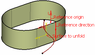
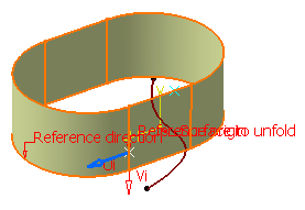
Select the Surface to unfold. For example Surface.1.

The surface must be connex and manifold. 
If the surface to unfold has no vertex belonging to one face (for instance, a closed surface as in our example), the reference origin and direction are not automatically valuated. On the contrary, they are valuated if a vertex on the edge of the surface is found. The result is positioned such as this origin and its image as well as the tangent to this direction and its image are coincident. -
Select the reference Origin, that is a point on the surface to unfold (here we selected Point.1).
-
If no specific origin is selected, it is set to Default. By default, when possible, a corner of the surface to unfold is selected.
-
If a target plane is defined and a projection is possible, the origin is defined as the projection of the point, selected as the origin on the surface to unfold, onto the target plane. If not, the origin of the axis system of the target plane is selected as the default origin.
-
-
Select the reference Direction. Here we select the edge of the surface on which the point lies.
-
Select the target Plane which the surface has to be unfolded.
The plane is defined depending on the origin and the direction of the surface to unfold. Here we set it to Default. -
Select the target Origin and the target Direction. These are enabled only if the target Plane is selected, else it is grayed out.
The target direction is determined by the plane tangent to the surface to unfold (Vi). -
Check Reverse Uf to reverse the final U direction, Reverse Vf to reverse the final V direction and Swap to reverse both Uf and Vf directions. If Swap is checked as well as Reverse Uf and/or Reverse Vf, the swap is performed prior to the inversions. These options are enabled only if the target Plane is selected.
-
Click Preview.
Flag notes display candidate curves to tear (if any) in the 3D area. The unfolded surface is positioned: - on the selected plane
- such as the image of the selected point on the surface to unfold coincides with the selected point on the plane, and
- such as the image of the tangent to the selected edge on the surface to unfold is collinear with the selected direction on the plane.


If you move the mouse over a flag note, a longer message giving an accurate diagnosis is displayed. The Curves to Tear tab lets you select as many internal and external curves or edges to tear as needed along which the surface is to be developed, so that constraints are solved. -
Select the curves to tear by either double-clicking the 3D flag or by directly clicking the curve or the edge.
If no edge of the surface can be defined as candidate, an information message is issued and the Curves to Tear tab displays a list of edges to be selected. The selection of curves or edges to tear is optional if there is no curve or edge to tear. To deselect a curve to tear, click Remove, and then click Preview. 
Unfold using an internal edge to tear 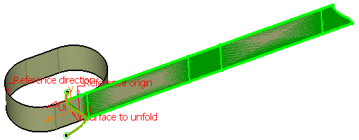
Unfold using an external edge to tear - To select an edge candidate to tear, double-click the information tag or click the edge directly in the 3D geometry.
- To select an edge to tear, click the edge directly in the 3D geometry.
-
Click OK to unfold the surface.
The developed surface (identified as Unfold.x) is added to the specification tree. 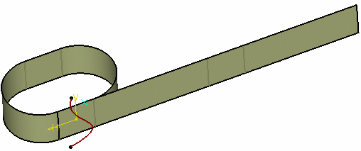
Unfold using an internal edge to tear 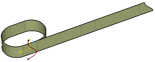
Unfold using an external edge to tear
Choosing the surface type
-
Click Unfold
.The Unfold Definition dialog box appears. -
Select the Surface to unfold and click Preview.
-
Click More>> to display further options:

-
Select the surface type to be unfolded:
-
Ruled (by default): to unfold a ruled surface only. If the surface is not ruled, an error message is issued.
-
All (in our scenario): to unfold any surface. If the surface is ruled, a warning message is issued offering you to switch to the Ruled type.
-
-
Select Display optional edges to tear to display the candidate curves or edges to tear in the 3D area:

This option is unchecked by default as well as at edition (even if checked previously). -
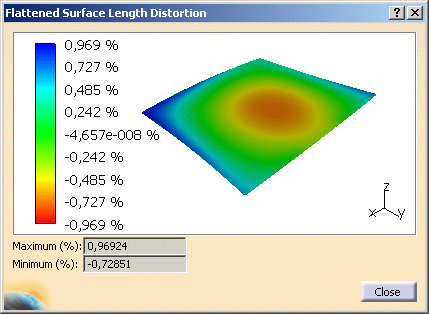
Click Display distortions to display the unfolded surface. The Flattened Surface Length Distortion displays the maximum and minimum percentages of length distortion. A positive distortion means that the flattened surface is stretched, while a negative distortion means it is shrunk.
The Display distortions button is grayed out at edition. To access it, you need to first modify an input and then click Preview.
Defining curves or points to transfer
-
Click Unfold
.The Unfold Definition dialog box appears.
-
Select the Surface to unfold and click Preview.
-
In the Transfer tab, select points or curves on the surface to unfold or on the unfolded surface.
-
Select the type of transformation:
-
Unfold: transfer the elements on the unfolded surface
-
Fold: transfer the elements on the surface to be unfolded
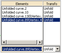
- Click Remove or Replace to remove the selected element or replace it by another element.
-
-
Click Preview to see the unfolded surface and elements.

-
Click OK to unfold the surface.
The developed surface (identified as Unfold.x) is added to the specification tree, as well as the transferred elements. 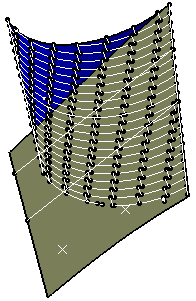
- Mono- and multi-cell surfaces, as well as closed surfaces can be unfolded.
- Multi-cell surfaces and surfaces with internal loops can be unfolded.
- If no point or direction that is not linked to the edges to tear can be selected on the surface to unfold, you can split the surface to unfold (using Keep both sides to retain the split element after the operation) and unfold both sides.
- It is not mandatory that surfaces be ruled: however, their resolution and parameterization must be geometrically identical to those of a ruled surface.
![]()