 |
This procedure describes how to
define a slot feature. A slot feature will appear as an activity
of the process on the PPR tree. |
 |
To define a slot feature, you
must have a product loaded. |
 |
-
Select the parent process or preceding activity for
the define slot activity.
-
On the Inspection Activities
toolbar, click
Define Slot . .
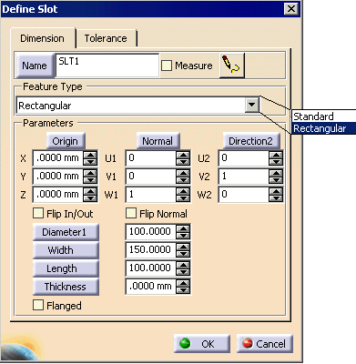
| The Define Slot dialog box appears. |
 |
| |
When you first create a feature, you need to select a
thickness for it. Inspect uses that thickness value as the
default value thereafter. |
-
From the pulldown menu, select a Feature Type.
-
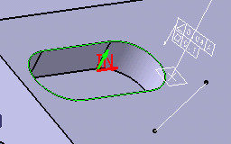
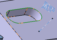
On the 3D geometry, select the slot.
| Once selected, the slot is highlighted, an arrow
showing normal protrudes through it, and its in/out orientation is
designated in red. The direction of normal or the direction
of in/out can be flipped by checking boxes on the dialog box. |
 |
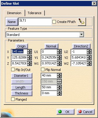
| The dialog box also contains the data for the slot
selected. |
 |
 |
You may enter a name for the slot in the name frame. |
| |
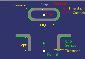
For an image defining the dimensions, click on the button. The image appears.
 |
| |
 |
| |
You can alter the slot's curve definition by clicking on the
Diameter button, and then selecting three points on the geometry
with which to redefine the slot's curve. |
| |
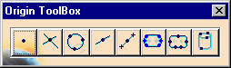
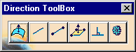
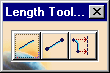
You can also alter the direction of Origin, Normal,
Direction2, Depth, Length, Width, and Thickness by selecting the
buttons with those parameter names. |
| |
If you select any of these buttons, the dialog box disappears,
and the appropriate toolbox appears in its place. Select the
button on the toolbar that changes the direction as desired. |
| |
 |
 |
See About the Toolboxes for
information on using the toolboxes. |
-
Select the OK button.
| The activity is added to the PPR tree. |
| The defined slot appears highlighted on the part geometry. |
 |
|
|
|
If you check the FPath
box, you can measure the feature at the same time you create it. |
| |
If you create a rectangular
slot, the options available are:
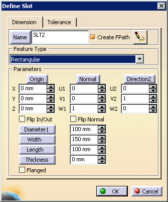
The measurement path alters to include the width measurement. |
| |
Checking Flip In/Out controls
how the measurement path is set relative to the feature. When the
option is checked, the measurement path follows the outside of the
feature; when it is not checked, the path keeps the probe inside the
feature The thickness also affects the path. If flange is set,
the measurement path will accommodate verifying the thickness of the
flange. |