 |
This procedure describes how to define a
group of points. Defining a group of points enables users to
inspect surfaces and curves.
Five strategies are available for defining a group of points:
- Grid approach: This approach enables you to
create a grid of points over a surface.
- UV approach: This approach makes use of the
imaginary iso-parametric curves (U-V) used to model any surface.
- Section approach: This approach
defines one or more section planes for inspection.
- Curve approach: This approach enables
users to select one or more curves on a surface or edge.
- Manual approach: This approach enables users
to select points on a surface.
The Define Group of Points dialog box has a variety of buttons.
In most cases, clicking on a button call up a toolbox that enables you
to select the desired value. For more information, see
About the Toolboxes for information
on using the toolboxes. |
|


 |
 |
Grid Approach
|
|
-
Select the parent process or preceding activity for
the define surface activity.
-
On the Inspection Activities toolbar, click
Define Group of Points . .
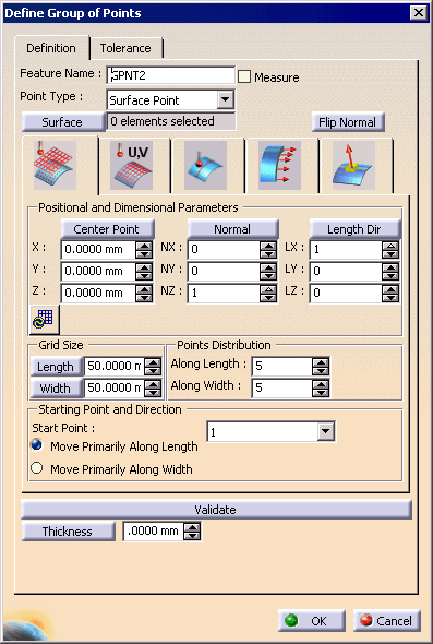
| The Define Group of Points dialog box appears: |
 |
-
Click on the Surface button.
| The Tool Palette appears to assist in surface
selection. |
-
Select one or more surfaces.
-
In Define Group of Points dialog box, click
on the Center Point button.
| A toolbox appears to assist in the selection. |
| You can also modify the values by using the spinners |
-
In Define Group of Points dialog box, click
on the Normal and Length Direction buttons, if
necessary.
| Each button causes a toolbpx to appear. You can also modify
the values by using the spinners. |
| The Autofit button can also be used to create an
approximation of the grid along the selected surface. |
-
Use the pull down menu to select a starting point (any
of the four corners are available).
-
Click on the Thickness button.
| A toolbox to appears. You can also modify the value by using
the spinners. |
-
For a preview of the grid, select the Validate
button.
-
Click the OK button when the grid is
created.
|
| |
U V Approach
|
| |
-
On the Inspection Activities toolbar, click
Define Group of Points . .
| The Define Group of Points dialog box appears. |
 |
-
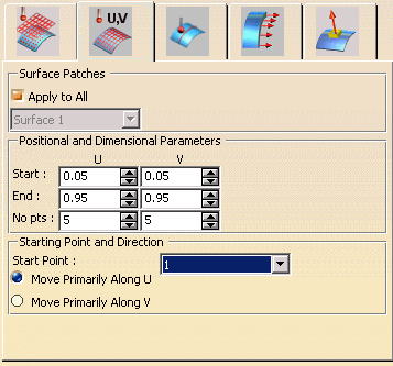
Select the U V tab (shown above).
-
Select one or more surfaces using the Surface
button.
-
Select the values for the tab, as described below.
| Since multiple surfaces can be selected, the dialog box has an
Apply to All option. If this is checked, then the
parameters shown in the dialog are applied to all the selected
surfaces, and the combo box listing the selected surfaces is
deactivated. When this check box is unchecked, users can assign
different parameter values for different surfaces. For this the
user selects the surface in the combo box and then assigns the
values for the selected surface. The selected surface is
highlighted in 3D viewer to help in associating the actual surface
with the parameters. |
| Start and End values for both U and V
parameters can be set in this tab. These values are normalized
between 0 and 1. Any of the corner points can be selected as the
Starting Point and the direction of point generation
can also be selected. |
-
Select the OK button.
|
| |
Section Approach
|
| |
-
On the Inspection Activities toolbar, click
Define Group of Points . .
| The Define Group of Points dialog box appears. |
 |
-
Select the Section tab (shown above)
-
Select one or more surfaces using the Surface
button.
-
Select the Add Section button.
| The Sectioning Definition dialog box and a
sectioning preview window appears. Also, the sectioning box
appears on the geometry view. |
 |
-
Define the section and click the OK button
on the Sectioning Definition dialog box.
-
Select the other values for the Section
tab, as described below.
| When the first section is created, the default position of the
section plane is at the world origin. For subsequent sections, the
default position and dimensions of the section plane are the same
as that of the last defined section. For editing/deleting a
section, user has to first press the corresponding push button and
then select the section in 3D.
The editor field below the push buttons for adding/removing
sections shows the total number of sections defined. When the
cursor is placed in this editor, all the sections are highlighted.
Since multiple sections can be defined, the dialog box has an
Apply to All option. If it is checked, the same
parameters are applied to all the sections. Otherwise, each
section has its own set of parameters. The current selected
section will be highlighted in 3D.
For information on Sag or No pts, see
below. |
-
Select the OK button on the Define
Group of Points dialog box.
|
| |
Curve Approach
|
| |
-
On the Inspection Activities toolbar, click
Define Group of Points . .
| The Define Group of Points dialog box appears. |
 |
-
Select the Curve tab (shown above).
-
Select one or more surfaces using the Surface
button.
-
Select the Select Curves button.
| The Edge Wizard toolbar appears.
The commands on the toolbar enable you to select the curve or the
elements of the curve with great precision. |
 |
 |
The EdgeWizard cannot be used on V4 data; for V4
data, you must select Pick Individual Curves. |
-
Use the Edge Wizard commands to select the
curve or curves.
-
Select the OK button in Edge Wizard.
| Since only continuous curves can be selected, users can select
the Treat as single curve option. When this is checked,
all the curves are treated as if they are merged into a single
curve. If five curves are selected and user wants to generate five
points, only 5 points will be generated in total.
If the Treat as single curve option is not selected,
then the five points will be generated on each curve.
When Treat as single curve option is checked, the
Apply to All option is both checked and deactivated.
Also, when the Apply to All option is activated, the
curve selection combo is deactivated. |
-
Select the other values for the Curve tab,
as described below.
|
The points are generated between the start and the
end parameter value of the curve. These values are normalized
between 0 and 1.
The Direction field enables the users
to select the direction of point generation. Also, the second
direction (perpendicular to both normal and the tangent) can be
flipped. This is more relevant in case of Trimmed/Hemmed/Roped
edge points.
Selecting No (number) points
generates the given number of points on the curve between the
given start and end parameter values. These points are equidistant
in the curve parameter domain. That is, if we have a straight
line, all points will be equidistant, but if we have a
non-straight curve, the points will be closer where the curvature
is more. The points are generated before the material check is
applied. Therefore, if there is no material below a point, the
number of points actually generated may be less than what is
specified. Also, the curve must lie on one of the selected
surfaces.
Selecting Sag is the maximum distance
between the curve lying between two points and the straight line
joining these two points. Therefore, the more the sag, fewer the
points generated and vice-versa. Also, more points will be
generated where the curvature is more. |
-
Select the OK button on the Define
Group of Points dialog box.
|
| |
Manual Approach
|
| |
-
On the Inspection Activities
toolbar, click Define Group of Points . .
| The Define Group of Points dialog box appears. |
 |
-
Select the Manual tab (shown above).
-
Select one or more surfaces using the Surface
button.
-
On the geometry select the desired points.
| Users can add points by simply clicking on the data in the 3D
viewer. Alternatively, they can select one or more existing points
and press the Duplicate Point button. This will
duplicate the selected points. Users can then translate the
selected points using the Translate spinners. New
points are inserted after the last selected row in the multi-list.
If no row is selected, new points are inserted at the end. After
the user selects the Validate or OK button,
the points are renamed so that they are in increasing order. The
name shown is merely symbolic.
When selecting points to move-up or down using the arrows, the
selected rows must be continuous. |
-
Select the OK button on the Define
Group of Points dialog box.
|


