This procedure has the following sections:
Measuring a Circle Feature
-
Select the parent process or preceding activity for the measure circle activity.
-
On the Inspection Activities toolbar, click Measure Circle
 .
. -
Select the defined circle you wish to measure.
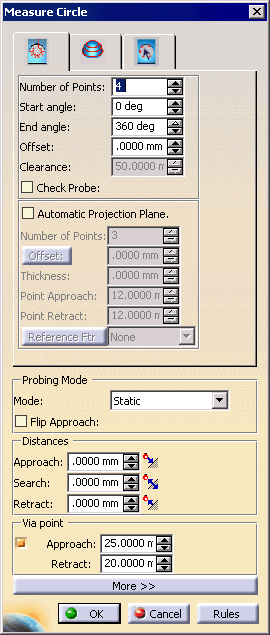
The Measure Circle dialog box appears. 
-
Alter the information in the dialog box as desired.
A preview of the path appears as you alter the data. 
-
Once you have defined the measurement desired, click on the OK button.
The activity is added to the PPR tree. Note that creating a measure circle activity also creates a tag list resource (which consists of circle path groups) and circle path applications. The measured circle appears highlighted on the part geometry.
Measuring a Circle using a JoPlug

-
Select the parent process or preceding activity for the measure circle activity.
-
On the Inspection Activities toolbar, select the Measure Circle icon:

-
Select the defined in-circle you wish to measure.
The Measure Circle dialog box appears; select the measure with JoPlug tab. 

The Parameters from the CSV File are either the default values or are those customized by the user. If users create their own CSV files, they can direct Inspection to the files by specifying the path in the Tools>Options>Inspection tab. When a parameter is selected, its data appears in the Current Selection box. The data in Current Selection can be altered. When edited, the start and end angles are checked to ensure that they are in the range of -360 to 360. If this condition is violated, a warning message appears. The out-of-range angles are set to -360 (if less than -360) or 360 (if greater than 360).
The Check Probe option is activated only if the start angle is 0 and the end angle is 360.
The following table provides the values for the default CSV table. Name Diameter Start Angle End Angle Incl Angle diam10 10 0 90 90 diam15 15 0 90 90 diam20 20 0 180 270 diam30 30 0 180 360 -
Alter the information in the dialog box as desired.
A preview of the path appears as you alter the data. A wireframe of the insert also appears. -
Once you have defined the measurement desired, click on the OK button.
Customizing the JoPlug CSV File
Knowledgeware Compatibility
IF HoleDiameter < 6 THEN ( MeasurementStrategy = JoPlug )
DMIS Export
Also, when material modifiers are applied to a geometrical tolerance (i.e., not to the datum reference frame), the DMIS will export an error.
-
The circle feature to be measured is exported.
-
A sphere with the spherical JoPlug's parameters (dia, position) is exported.
-
The measurement points for the above sphere is exported.
-
A plane with the circle feature's position and normal is exported.
-
The sphere in step 2 is projected on to the plane and a point is constructed. This point is exported.