To define a thread, you can enter the values of your choice, but you can use standard values or personal values available in files too.
This task shows you how to create a threaded hole using values previously defined in a file.
-
Click the Hole icon
 if you wish to create a hole in Part Design, or click the Hole
icon
if you wish to create a hole in Part Design, or click the Hole
icon
 to
create a hole in Functional Molded Part.
to
create a hole in Functional Molded Part. -
Select the face on which you wish to create the hole.

-
In the Hole Definition dialog box that displays, define the hole shape and enter the parameters of your choice. For more information, refer to Creating Holes.
-
Click the Thread tab.
-
Check Threaded to access the thread definition options.

In the Type field, you can choose among three different thread types:
- No Standard: uses values entered by the user
- Metric Thin Pitch: uses ISO standard values
- Metric Thick Pitch: uses ISO standard values
In addition to these three types, you can add your personal standards as described in Reusing Values Already Defined in a File
- You can modify a standard on the fly. But if the standard has already been used, the modification is not taken into account in the Hole Definition and Thread Definition dialog boxes.
-
Value 15mm does not exist in selected standard. Diameters will
			be set with the first line of the standard.
-
Do not modify a standard (a .txt file) after using it. We recommend you create a new standard instead.
By navigating to the file you need
-
Simply click Add to access this file.
A dialog box displays, in which you can navigate to reach the file containing your own values. This file may be of one of the following types:-
Microsoft Excel files (general format)
-
Lotus files
-
tabulated files (in Unix environment)
The file types supported are the same as those used for design tables.
The values defined in your file will apply specifically to the part of your CATPart document, not to other documents.
-
-
Navigate to StandardGaz.txt file and click Open to get the values it contains.
The Hole Definition dialog box reappears. Your file looks like this:
The file was created as follows:
Nominal diameter Pitch Minor Diameter Key - The first row contains no numerical values
- the other rows below are reserved for numerical values, except for the last column which contains descriptions very often represented by letters.
- the mandatory items are keys that define the names associated with the values.
Moreover, the name of the standard is the same as the name of the file without the extension. You should remember these recommendations for creating your own personal files.
-
Set the Type option to StandardGaz.
-
In the Thread Description field, set G7/8.
The Edit formula... contextual command is now available from the Thread Description field, meaning that you can define formulas for managing diameters values.
You can note that the values associated with the G7/8 key (see the contents of the StandardGaz file) appear in the Hole Diameter field as well as the Pitch field (distance between each crest) are provided in the corresponding fields.
You cannot edit these fields.
By selecting the file from the Type list: the file is already available
This behavior is made possible only if the administrator has performed these operations:
-
The administrator first needs to locate in a directory the source files used for the standards. For example, he can select E:/user/standard as the directory containing the StandardGaz.txt file.
-
Then, he has to concatenate this path with the official path in the CATReffilesPath environment variable as follows: The result is the following: whenever the Hole command is launched, the application identifies all standards provided by the administrator. The user does no need to navigate to the file any longer.

-
If necessary, edit the thread depth then the hole depth if you need to modify the value you had previously set in the Extension tab. This value must not exceed the thread diameter value.
-
Check the Left-Threaded option.
-
Click OK to confirm your operation and close the Hole Definition dialog box.
The application displays the hole in the geometry area but not the thread. Note also that an icon specific to this feature is displayed in the specification tree.

You can use a planar geometrical element as limiting thread/tap depth element or set the Thread Depth with the length of the support. The Bottom Type frame provides three different options to set depth:
|
The Bottom Limit option specifies the bottom limit for the element. This option is only available with the Up-To-Plane bottom type. It has a contextual menu in order to create a planar element on the fly. The Thread Depth field will get disabled with the selection of Up-To-Plane or Support Depth option.
The Bottom Limit element must be planar and parallel to the Limit Face.
Thread Types
No Standard
If you keep the No Standard option, the field available below is Thread Diameter. You just need to enter the values you need in this field as well as in the fields below.
The Edit formula... contextual command is available from the Thread Diameter field, meaning that you can define formulas for managing diameters values.
Metric Thin Pitch: ISO standard
Refer to ( ISO 965-2 ). The application uses the minimum standard values.
| Nominaldiam | Pitch | Minordiam |
| 8.0 | 1.0 | 6.917 |
| 10.0 | 1.0 | 8.917 |
| 10.0 | 1.25 | 8.647 |
| 12.0 | 1.25 | 10.647 |
| 12.0 | 1.5 | 10.376 |
| 14.0 | 1.5 | 12.376 |
| 16.0 | 1.5 | 14.376 |
| 18.0 | 1.5 | 16.376 |
| 18.0 | 2.0 | 15.835 |
| 20.0 | 1.5 | 18.376 |
| 20.0 | 2.0 | 17.835 |
| 22.0 | 1.5 | 20.376 |
| 22.0 | 2.0 | 19.835 |
| 24.0 | 2.0 | 21.835 |
| 27.0 | 2.0 | 24.835 |
| 30.0 | 2.0 | 27.835 |
| 33.0 | 2.0 | 30.835 |
| 36.0 | 3.0 | 32.752 |
| 39.0 | 3.0 | 35.752 |
| 42.0 | 3.0 | 38.752 |
| 45.0 | 3.0 | 41.752 |
| 48.0 | 3.0 | 44.752 |
| 52.0 | 4.0 | 47.67 |
| 56.0 | 4.0 | 51.67 |
| 60.0 | 4.0 | 55.67 |
| 64.0 | 4.0 | 59.67 |
Metric Thick Pitch: ISO standard
Refer to ( ISO 965-2 ). The application uses the minimum standard values.
|
Nominaldiam |
Pitch | Minordiam |
| 1 | 0.25 | 0.729 |
| 1.2 | 0.25 | 0.929 |
| 1.4 | 0.3 | 1.075 |
| 1.6 | 0.35 | 1.221 |
| 1.8 | 0.35 | 1.421 |
| 2.0 | 0.4 | 1.567 |
| 2.5 | 0.45 | 2.013 |
| 3.0 | 0.5 | 2.459 |
| 3.5 | 0.6 | 2.850 |
| 4.0 | 0.7 | 3.242 |
| 5.0 | 0.8 | 4.134 |
| 6.0 | 1.0 | 4.917 |
| 7.0 | 1.0 | 5.917 |
| 8.0 | 1.25 | 6.647 |
| 10.0 | 1.5 | 8.376 |
| 12.0 | 1.75 | 10.106 |
| 14.0 | 2.0 | 11.835 |
| 16.0 | 2.0 | 13.835 |
| 18.0 | 2.5 | 15.294 |
| 20.0 | 2.5 | 17.294 |
| 22.0 | 2.5 | 19.294 |
| 24.0 | 3.0 | 20.752 |
| 27.0 | 3.0 | 23.752 |
| 30.0 | 3.5 | 26.211 |
| 33.0 | 3.5 | 29.211 |
| 36.0 | 4.0 | 31.670 |
| 39.0 | 4.0 | 34.670 |
| 42.0 | 4.5 | 37.129 |
| 45.0 | 4.5 | 40.129 |
| 48.0 | 5.0 | 42.587 |
| 52.0 | 5.0 | 46.587 |
| 56.0 | 5.5 | 50.046 |
| 60.0 | 5.5 | 54.046 |
| 64.0 | 6.0 | 57.505 |
Reusing Values Already Defined in a File
There are two ways of accessing values listed in a file: either by navigating to the file of interest or by making this data available prior to launching the Hole command. For more, see the file is already available.
A Few Words About Removing Files
The Remove button removes files containing user-defined values. You cannot remove files containing standard values.
Clicking the Remove button displays the list of user-defined files. You then just need to select or multi-select (using ctrl key) the files and click OK to confirm the operation.
 |
Note also that you cannot remove a standard file if it is used for a hole created in the CATPart document.
Threading Counterbored Holes
The thread depth value you enter to thread counterbored holes does not apply to the counterbored part of the hole. The thread depth for counterbored holes corresponds to the distance shown by the yellow arrow on the help image:
 |
Threading Tapered Holes
You can thread tapered holes in the same way as you thread any other hole types. Once you have selected a tapered hole, the image in the dialog box assists you:
 |
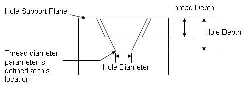
The following figure illustrates how the different parameters you need to value are defined:
 User Features and Power CopiesUser Features and Power Copies do not support standards used in the definition of thread features. |