This step creates points on the robot, or a product to which a cable can connect. If the robot already has connectors defined on it, then proceed directly to creating a cable between the connectors.
Since this is a complex process we are going to step through, in depth, a scenario to create a Robot cable.
In the Device Building workbench, Start with a empty Product.
(If you need a Product window, from the Main menu, select, File > New.
In the dialog box select Product, and OK)
![]()
From the main menu, select
Insert > Existing Product, and click on Product1 in the tree.
The File Selection dialog box appears. Select a robot to
load.
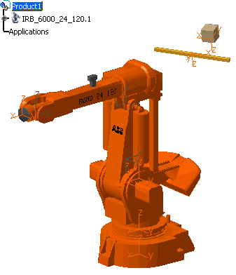
This ensures that the cable that we are going to create is separate from the robot, but still in the same product.
-
Click Define Connector
 ,
and the command prompt requires you to select a product with no
electrical behavior (except connector behavior for edition).
 Select the part of the robot to which we want to connect one end of the cable either in the specification tree or in the geometry area. In this scenario we are going to select the brown box from the PPR tree for the one end of the cable to connect to. (This way it ensures you get the whole part, not sections).
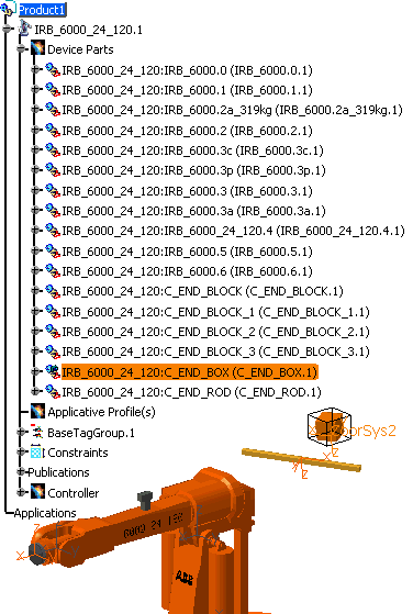
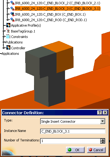
The Connector Definition dialog box appears.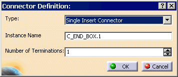
- The only type available is Single Insert Connector: male or female connector applicable to electrical layout.
- Change the name in the Instance Name field if necessary.
- Enter the Number of termination to be defined
onto the connector.
The terminations are used to connect the cables.
-
Select the defaults, and for the Number of Terminations, select 1. Click OK to validate the window.
-
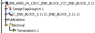
After successful execution of this command the specification tree is updated. The part is not modified.
The instance of the connector is now an electrical object as the electrical behavior has been added.
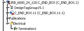
-
Next, define the constraints at the points at which the other end of the cable will be connected to the Robot. Following the same procedures, Click Define Connector
 ,
and the command prompt requires you to select a product with no
electrical behavior (except connector behavior for edition).
 -
In this scenario, select the C_END_BLOCK_3.1. The dialog box appears, and change the Number of Terminations to 1.
-
The PPR tree is updated.
-
Both ends of where the cable is going to be attached are created.
-
Next, we have to define the bundle connection points at the points at which the cable ends will be connected.