For this scenario, we will be utilizing the Equipment & Systems > Electrical Harness Discipline > Electrical 3D Design Part workbench to create the constraints.
-
Once Creating Connection Point Constraints, Click Define Connector
 ,
and select a part or product.
,
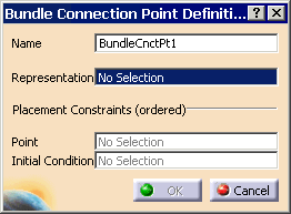
and select a part or product.Select from the PPR tree the connector C_END_BLOCK_3. The Bundle Connection Point Definition dialog box appears. 
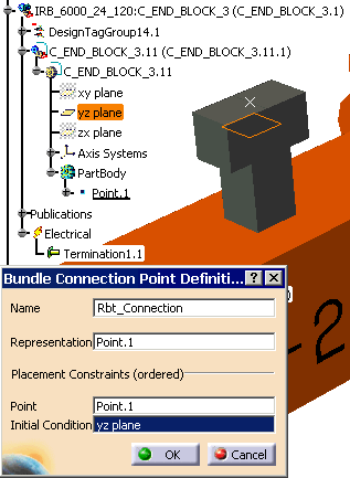
- Change the Name to Rbt_Connection
- For the Representation select the point. A representation can be a point or a surface.
- For the Point, select the Point again. This point will possibly be used as bundle segment extremity.
- For the Initial Condition, select the yz plane. This plane or axis will determine the direction in which the cable will come out of the connection point. (right-click the yz plane, and hide/show if not available)

- Select OK when completed.
-
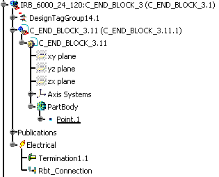
The Rbt_Connection appears in the PPR tree.

-
Click Define Connector
 ,
and select a part or product.
,
and select a part or product.Select from the PPR tree the connector C_END_BOX_1. The Bundle Connection Point Definition dialog box appears. NOTE: you must type in a name, as the default name can only be used once, then it will give you a error.

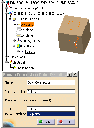
- Change the Name to Box_Connection
- For the Representation select the point
- For the Point, select the Point again
- For the Initial Condition, select the xy plane

- Select OK when completed.
-
The Box_Connection appears in the PPR tree.

-
Save your scenario.
-
Next, we have to define the Geometrical Harness for the connection points that were created.