-
Click the Create 3D Multi-Splice icon
 .
.
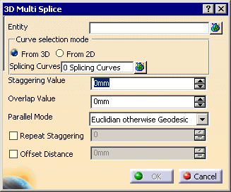
The 3D Multi-Splice dialog box is displayed.
-
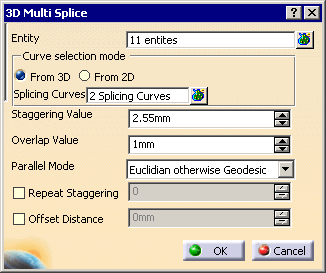
In the Entity field, select the plies to which you want to apply a 3D Multi-Splice.
In our example, we selected Ply.20 to Ply.30.
-
Choose the From 3D Curve selection mode:
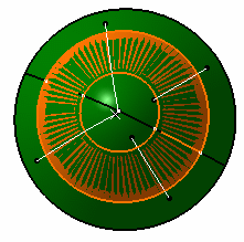
This option allows splicing with curves lying on the ply/plies group surface. - Click
 and select Line.1 and Line.2 and set the
values for the
Staggering Direction
and the
Overlap
Direction as shown below.
and select Line.1 and Line.2 and set the
values for the
Staggering Direction
and the
Overlap
Direction as shown below.

- Curves must be selected in the right order.
-
The Directions are previewed in the 3D geometry.
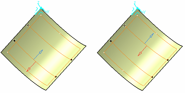
This is the option proposed by default.
- Click
-
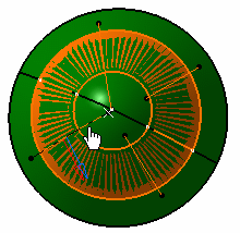
Define the Staggering Value and the Overlap Value with the up and down arrows as shown below.
-
Select a Parallel Mode:

-
If required, select the Offset value check box and enter an offset value.
-
Click OK.
The specification tree is updated accordingly.
3D Multi-Splice on Cylindrical Plies
-
Click the Creates 3D Multi-Splice icon
. -
In the Entity field, select the cylindrical plies on your part.
-
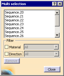
Click the Multi-selection icon at the right of the Splicing Curves field and select the curves on the geometry.
-
Define the Staggering Value and the Overlap Value with the up and down arrows.
-
Click OK to create the splices on the cylindrical plies.
The 3D Multi-Splice feature is created and includes:
- the selected plies,
- the splicing curves,
- the staggering value,
- a staggering direction per curve,
- the overlapping value,
- an overlapping direction per curve.
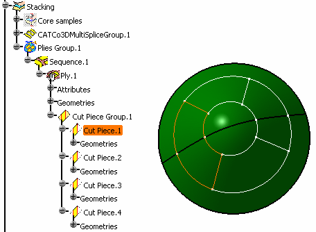
Sub-plies (also called cut-pieces) are created under each ply and have the following characteristics:
-
they inherit the material and direction of the ply,
-
their contour is associative with the father ply geometry in the following cases:
-
the ply surface is modified,
-
the ply geometry is modified e.g. the boundaries of the plies are modified or a limit contour is applied to the ply,
Note however that the number of cut-pieces is not modified during the update of the part, e.g.:
Original situation
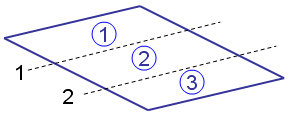
Situation after update
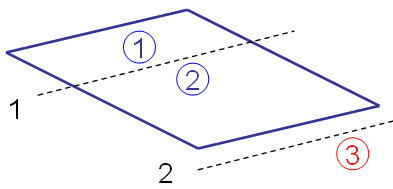
Curve 2 no longer intersects the father ply geometry
The limit contour feature of cut-piece 3 will have an update error
You must delete the cut-piece manually. -
- they have their own rosette and producibility feature,
- they have their own geometry and can be modified individually,
-
They are taken in account in the following commands:
Ply exploder
Limit contour
Core sampling
Numerical analysis
Material excess
Skin swapping
Creates manufacturing Document
Synchronizes this document - they can be used for any manufacturing export,
- they can be transferred in the manufacturing model if generated in the engineering model.
![]()