 |
This task shows you how to define Grid Panels in three steps, each
step having its own dialog box:
Note that the last two options are not proposed if the reference
element has not been created from a surface. |
|
|
- This task is available in the CATIA Composites Engineering (CEG)
product.
- This task is available in the Composites Grid Design workbench.
|
 |
- The last two options are not proposed if the reference element has
not been created from a surface.
- You can edit the parameters of a structural group or a structural
element via a formula.
- When you edit a structural group, you apply the values of those
parameters as formulas to all the reference elements of the group.
|
 |
Open PanelStart01.CATPart
from the samples directory. |
 |
-
Click
Grid Panel definition
 . .
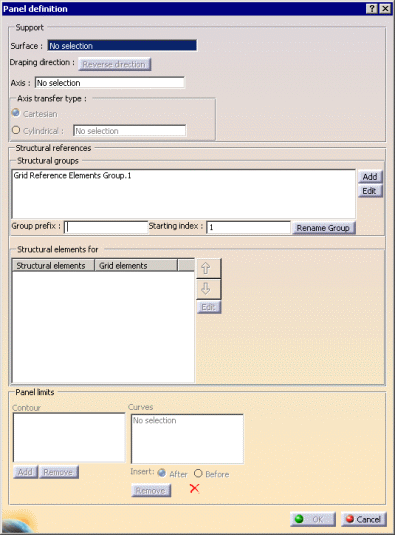
The Panel definition dialog box is displayed.
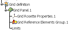
A Grid definition node is created in the specification tree.
A
Grid Reference Elements Group is proposed in the dialog box and
created in the specification tree.
For the moment it is empty.
Its default name is
Grid Reference Elements Group.x.

You can edit this name: Key in the required name in
Group prefix and click
Rename Group.
-
Select MOLD as the
Support Surface.
Note that holes are not allowed on the support surface.
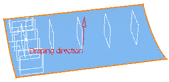
The
Draping direction is displayed in the 3D viewer.
If necessary, click Reverse direction in the dialog box,
or click the red arrow in the 3D viewer to invert the Draping
direction.
-
Select Absolute Axis System as the
Axis (i.e. the rosette) in which
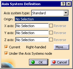
the directions are referenced. If the axis system does not yet exist,
create it:
- Place the cursor in the Axis field and
right-click to display the contextual menu.
Select the Create Axis System item:

- Define the axis system in the dialog box that appears:
|
-
If necessary, select the type of axis transfer
to be applied in Angle cut definition,
Producibility,
Producibility Inspection
or
Fiber Direction:
- Cartesian:
this rosette transfer type is suitable for panels with a low
curvature.
-
Cylindrical: this rosette transfer type is suitable for
parts with a high curvature.
This mode requires that you select a Neutral Fiber, i.e.
the axis of the cylindrical shape to be used. The X-axis of the
rosette will correspond to this neutral fiber.
|
-
Create one
Structural group with the
Group prefix H:
- Select the grid Reference Elements Group.1 in the dialog box
and enter H as the Group prefix:

- Click Rename Group. The name is updated:

- Select the elements in the 3D view. Structural elements
(e.g. ribs and stingers) can be either:
- curves,
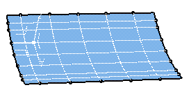
- or surfaces or planes.
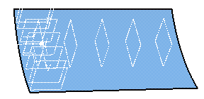
- A warning is displayed if several structural elements have the
same name.
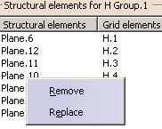
- A contextual menu is available to remove or replace a
structural element, as well as arrows to reorder them:
- If a Grid has been created, new cells can appear or others
can be removed. In that case, the Stacking Areas Table, Sequence
Shape even the Plies contours will be updated.
- If you edit an existing Grid Panel and you need
to edit a Structural group, select it in the dialog
box to display the list of its elements.
|
-
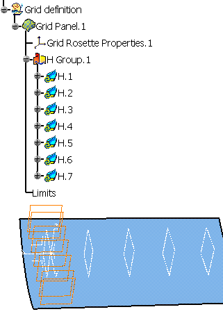
They are added to the specification tree and to the
dialog box:
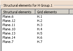
-
A grid panel may contain several Structural groups.
Click Add in the Structural groups frame.
A new Structural group is added both in the dialog box and in the specification tree.
Enter V as the Group prefix and select the
vertical planes.
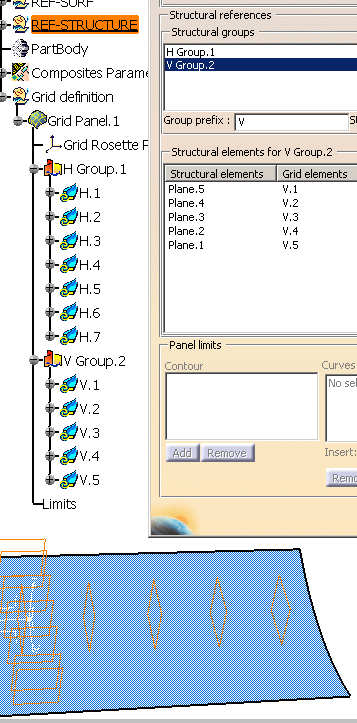
A contextual menu is available to remove Structural groups:

|
| |
-
Optional: define the
limits of the panel (i.e. the Edge of
Part). They will show the
part boundaries and its holes.
-
Click Add in the Panel limits frame.
A contour is added in the dialog box.
-
Select curves so that they form a closed contour.
A green tip replaces the red cross.
-
Use Insert After, Before
and Remove to modify the order of the curves as well as
the contour.
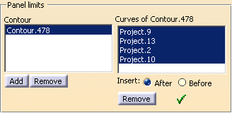
-
Use the contextual menu to create the curves of the contour
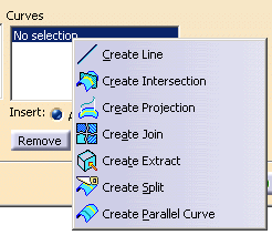
|
|
 |
If you define the Limits of the Grid Panel, the ExtrapolDist parameter that has been defined in the
Zone Definition dialog box is
stored under the contour of the Grid Panel.

It is visible in the dialog box when you re-open it:
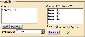
- If you are editing an existing Grid Panel, this parameter is
editable too.
- If you are editing an existing Grid Panel, and change
the Side attribute of a limit contour, a warning message will be
displayed as this will impact the ply.
- An arrow lets you decide of the limitation side of limit contours.
- You can define several Grid Panels in the same CATPart.
|
| |
-
Click OK to validate and exit the dialog box.
The Grid Panel is created in the specification tree:
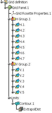
and in the 3D view:
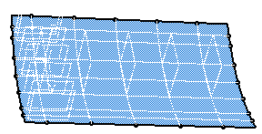
|
| |
-
To edit a structural group, either:
- select it in the Panel definition dialog box, add click
Edit,
- or, once it has been created, double-click it in the
specification tree,
- or, once it has been created, right-click it
in the specification tree and select Definition in the
contextual menu:

Select H Group.1 and click Edit in
the Structural Groups frame.
The
Default Staggering definition for S_Group.1 dialog box is
displayed.
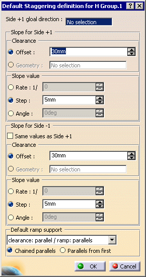
|
-
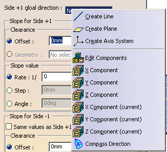
Enter the global direction for Side +1.
A contextual menu is available to enter the global direction:
-
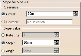
Define the slope applied to Side+1
-
You can then apply the same values to Side -1 or define
different values.

-
Define the Default ramp support.
-
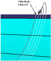
Select an option to create the parallels:

- Chained parallels: each parallel is created from the last
created one.

- Parallels from first: all the parallels are created from
the first one.
|
-
Click OK to validate and return to the main
dialog box.
-
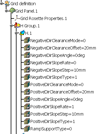
Click OK to validate and exit the Grid Panel definition dialog box.
The values entered are stored as parameters under each element Element
of the group.
|
| |
-
To edit a structural element, either:
- select it in the Panel definition dialog box, click
Edit,
- or, once it has been created, double-click it in the
specification tree,
- or, once it has been created, right-click it in the
specification tree and select Definition in the
contextual menu:

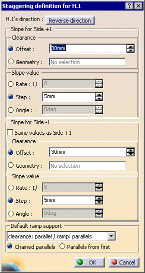
- The Staggering definition for Grid Reference Elements is
displayed:
|
-
The direction of the structural element is displayed in
the 3D viewer.
Click Reverse direction in the dialog box or the arrow in the
3D viewer to invert that direction.
-
Enter the values that will apply to the element
selected, as you did for the structural group.
-
Click OK to validate and return to the main
dialog box.
-
Click OK to validate and exit the command.
The values entered are stored as parameters under the element selected and
have replaced those entered for the group.
|
 |
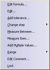
- You can edit the parameters of a structural group or a structural
element via a formula:
- When you edit a structural group, you apply the values of those
parameters as formulas to all the reference elements of the group.
|
|
 |
