Creating Functional Electrical Components
| Having created a system, you are now
ready to define the components making up this system. |
 |
 |
Create equipment: Select a system, choose
the Equipment type then enter the name(s) and attributes of
equipment to create in the BOM view and click OK. |
 |
Create connectors: Select an item of
equipment or a system, choose the Connector type then enter the
name(s) and attributes of connector(s) to create in the BOM view and click
OK. |
 |
Create contact points: Select an item of
equipment or a connector, choose the Contact Point type then
enter the name(s) and attributes of contact point(s) to create in the BOM
view and click OK. |
 |
Create signals: Select a system, choose
the Signal type, then enter the name(s) and attributes of
signal(s) to create in the BOM view and click OK. |
 |
Copy & paste components: Select the item
to copy, click the Copy icon then select the target parent
component and click the Paste icon. |
 |
Create off sheet connectors: Select a
signal, click the Off Sheet Connector icon, then enter the
name(s) and attributes of off sheet connector(s) in the BOM view and click
OK. |
|
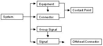
The tasks in this section step you through the creation of
some of the functional electrical components shown on the schematics
diagram below: |
|
 |
|
 |
Validating information means that the data is sent to the
server. If knowledgeware is used, the server checks data received and if
necessary, corrects it then sends the updated view back to the client.
In BOM views, information
is validated when you click OK, when you change the current
object in the tree view or when you change the active view. |
|
 |
A star appears in the tree view beside systems that have been modified
and require saving. |
|