The command allows you to define three types of patterns:
- Rectangular as illustrated in the scenario below.
- Circular
- User Pattern
To create a rectangular pattern, you need to choose one or two creation directions as well as the types of parameters you wish to specify so that the application will be able to compute the location of the items you copied. This task shows you how to create a rectangular pattern from three functional features.
-
Click the Pattern icon
 .
.
The Pattern dialog box is displayed. Default options let you define a rectangular pattern.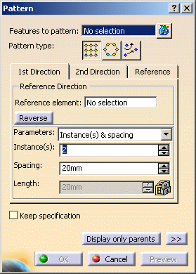
Keep Specifications Option
Checking the Keep specification option creates instances where a limit (To Plane/Surface, To Shell, Extend across removed faces, Trim to Shell) defined for the original feature is used for each instance. In the example below, the limit defined for the prism, i.e. the To Plane/Surface limit, applies to all instances. As the limiting surface is not planar, the instances have different lengths.
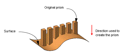
But for the purposes of our scenario, as the limit defined for the prism is Length, activating the Keep specification option is meaningless.
-
Select Protected Prism.5 as the feature to pattern.

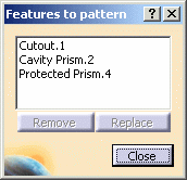
When you select several features, the field displays the number of selected elements. To act on this selection, just click the
 icon to display the
Features to pattern dialog box that allows you to:
icon to display the
Features to pattern dialog box that allows you to:- view the selected elements
- remove any element clicking the Remove button
- replace any element using the Replace button and selecting a new one in the geometry or the specification tree.
1st Direction
-
To define a direction, you can select a line or a planar face. Select the xy plane to specify the first direction of creation.
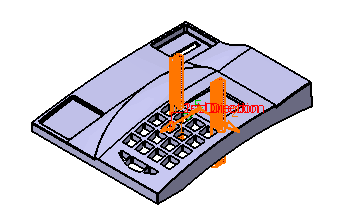
An arrow indicating the direction is displayed on the functional body. -
Check the Reverse button or click the arrow to reverse the direction.
The new direction is as follows:
Contextual commands creating the reference elements you need are available from the Reference element field:
- Create Line: For more information, see Creating Lines.
- X Axis: the X axis of the current coordinate system origin (0,0,0) becomes the direction.
- Y Axis: the Y axis of the current coordinate system origin (0,0,0) becomes the direction.
- Z Axis: the Z axis of the current coordinate system origin (0,0,0) becomes the direction.
- Create Plane: see Creating Planes.
If you create any of these elements, the application then displays the corresponding icon next to the Reference element field. Clicking this icon enables you to edit the element.
-
Define the parameters you wish to specify. The parameters you can choose are:
- Instances & length
- Instances & spacing
- Spacing & length
Keep the Instances & spacing options.
-
Enter 5 as the number of instances you wish to obtain in the first direction.
-
Define the spacing along the selected direction: enter 9.5 mm.
The pattern looks like this: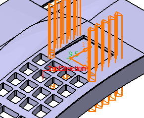
2nd Direction
Defining a second direction is not compulsory. Creating a rectangular pattern defining only one direction is possible, but if you need to use a second direction, click the 2nd Direction tab to define other parameters.
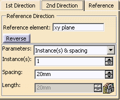
-
Click OK to confirm the operation.
The rectangular pattern composed of 10 instances is created:

Rectangular Pattern.X is added to the specification tree in the Solid Functional Set.X node.
Reference
Clicking the Reference tab displays three options allowing you to modify the location of the instances with respect to reference features.
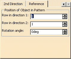
You can change locations in both directions. For example, if you enter 3 in Row in direction 1 , the instances are moved along direction one in three times:

You can also rotate the pattern by specifying a rotation angle value. For example, entering 15 deg, the pattern is rotated counter-clockwise and looks like this:

Removing Instances
Clicking an instance once removes the instance from the specifications.