The system tries to combine the selected surfaces to form common areas, and to keep the transition qualities as far as possible during the offset computation. If required, the offset surfaces are trimmed or extrapolated
-
Click the Global Surface Offset icon
 .
.
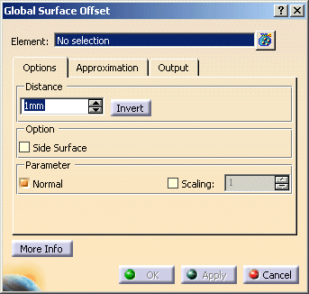
The 'Global Surface Offset' dialog opens.

-
Select the surface you want to modify.

-
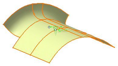
Specify an offset distance of 5 mm and click Apply to create the offset surface.

-
Click OK to exit the command.
- Elements: Selection of the surfaces to be offset.
- Distance
- Text field: Specifies the distance of the offset surfaces from the original surfaces (offset distance).
- Invert: Inverts the direction of all offset vectors.
- Option:
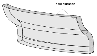
- Side Surface: Connecting surfaces are generated between original and offset surface.

- Parameter
- Normals: Display of the direction of the original surfaces in the graphics area. With the manipulator, you can change the distance and invert the direction.
- Scaling: The size of the manipulators at the geometry can be scaled.

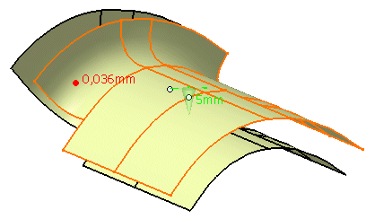
- Display: The graphical display of the deviation values can be globally switched on and off.
- Deviation
- Max: Display of the maximum deviation of the actual result from the calculated mathematical result.
- Output Result: See Output Result
![]()