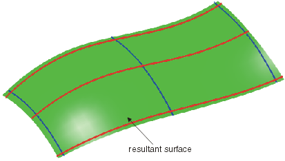
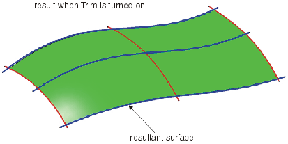
 |
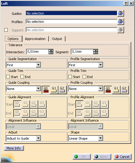
You can define the following options:
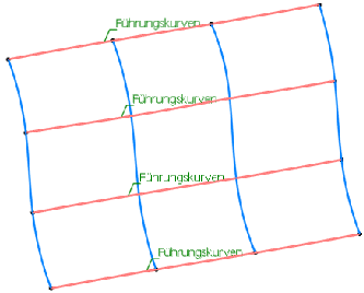
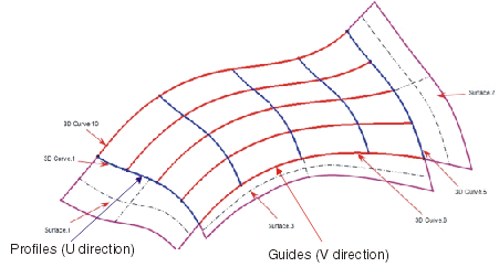
- Guides: Selection of one or several curve elements as guides (V direction).
- Profiles: Selection of one or several curve elements as profile (U direction).

 |
Note: The curve elements selected as guides and profiles must all lie in the corresponding
direction, as otherwise the selection will not be considered as valid input.
 |
|
| |
Contextual menu
|
| |
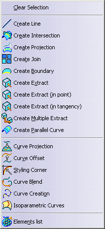
Available from the Guide and Profile selection fields is the following contextual menu to allow interactive input
selection and stacked command capabilities. |
 |
| |
- Support: Selection of the elements used to provide edge continuity.
Default setting is G0.
Continuity available on each selected element is G0, G1, and G2.
|
| |
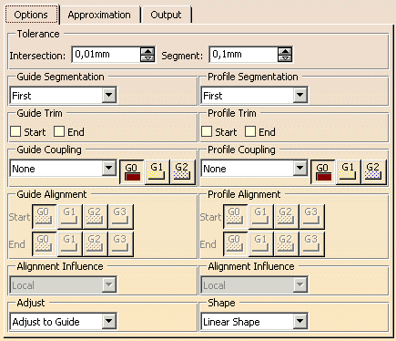
Options tab |
 |
| |
- Tolerance:
- Intersection: The Intersection tolerance is a tolerance value in which the selected
profile and guide curves must intersect each other in order for a result to be created. If one or several curves are
not within this tolerance, the result cannot be created and a corresponding error message is displayed.
Moreover, the Intersection tolerance defines the maximum distance to the support surfaces which influence the continuity
condition of the result.

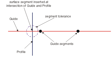
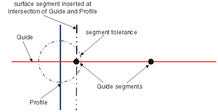
- Segment: The Segment tolerance determines the segment boundaries of the resulting surface at the intersection
point between guide and profile according to the following criteria:
- If the value is exceeded at the point of intersection, the segment position in the result uses the guide and profile
curve intersection for the segment position irrespective of the internal segmentation of the curves used.
- If the tolerance value is met at the point of intersection, then the segment position in the result uses a segment
point in the curves used.
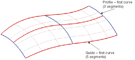
- Guide/Profile Segmentation: The segmentation priority options allow to influence the result according to the
segmentation points on the guides and profiles.
- First: The segmentation will be taken from the curve defined as first guide or profile from the selection
process. All other curves are ignored.
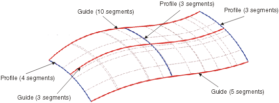
- Max.: The segmentation will be taken from the guide or profile with the maximum number of segments.
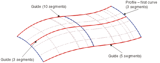
- All: The segmentation of the result will be calculated from the segment boundaries of all guides and profiles.
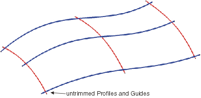
- Guide/Profile Trim: Input curves that do not have coincident ends can be trimmed temporarily.
The user can choose either the Start or End or both options depending upon the result needed from the input curves.
The resultant surface is then created between temporary trimmed guides and profiles.
- Guide/Profile Coupling: These options allow to manage the internal parameterization of the resultant surface
as it passes through guides and profiles.
For the specification of the parameterization of the coupling between each set of curves the following options are available:
- None: The coupling is defined automatically by the command, and the user has no control over the re-parameterization
of the profiles.
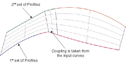
- Segments: The calculation of the coupling is defined by the number of segments contained within the set
of curves defining the profiles and guides allowing the user to re-parameterize according to the internal continuities.
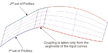
- Cells: The calculation of the coupling is defined by the number of cells (individual curves) defining the
profiles and guides allowing the user to re-parameterize according to the internal continuities.
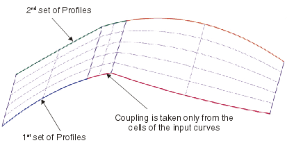
- Bends: The calculation of the coupling is defined by the number of bends (cells and segments) defining
the profiles and guides allowing the user to re-parameterize according to the internal continuities.
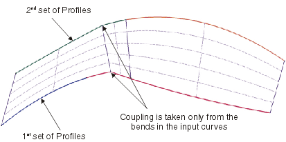
- Guide/Profile Coupling Continuities: The continuity options are only available with the options Segments,
Cells, and Bends.
The options will impose a level of continuity on the selected curves, thus reducing the number of cells within the result
depending upon the inputs.
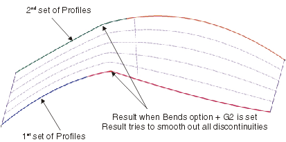
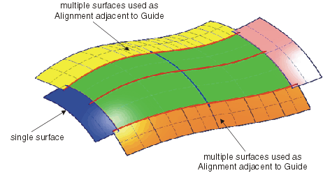
- Guide/Profile Alignment: These options allow to influence the continuity condition of the selected Start and
End curves for either guide or profile to an adjacent set of support surfaces.
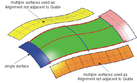
The support surfaces used for each side can be more than one surface and their order adjacent to the Guide or Profile curves
is managed by the command, meaning the user is not required to organize their data before commencing the construction of
the Loft surface.

Accepted alignment criteria:The images below demonstrate the type of acceptable alignment criteria used to influence
the alignment continuities.
- Alignment Influence:
- Local: The continuities assigned to a specific edge only influence the surface shape locally between the
1st and 2nd curve according to the continuity specified.
As a result of local continuity matching, the result in addition attempts to pass through the guide and profile curves.
Therefore depending upon the continuity settings, the positions of the curves and the approximation settings, result
attempts to create a non oscillating result.
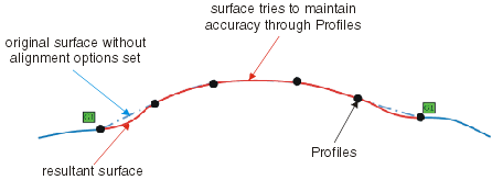
- Spread: The continuities assigned to a specific edge influence the surface shape through all the selected
internal guide and profiles according to the continuity specified.
Therefore depending upon the continuity settings, the positions of the curves and the approximation settings, an oscillating
result may be produced.

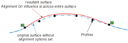
- Global: The continuities assigned to a specific edge, influence entire surface shape. Depending upon the
approximation settings the result accuracy to the guide and profile curve inputs can be lost.
- Adjust: This interpolation option allows you to select which priority is assigned to the calculation of the
result depending upon the inputs.
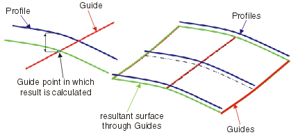
- Adjust to Guide: The priority for calculating the result is given to the Guides
When the option 'Guides' is set, the result is calculated giving the profile curves the most influence over the final
result. The Profiles are then used as a guide to assist in achieving the smoothest transition of the result between
the Guides.
The Approximation settings used will effect the accuracy of the result from the true mathematical result and the final
result. Any deviation is displayed in the deviation frame in the UI and in the graphics.
- Adjust to Profile: The priority for calculating the result is given to the Profiles
When the option 'Profiles' is set, the result is calculated giving the profile curves the most influence over the final
result. The guides are then used as a guide to assist in achieving the smoothest transition of the result between the
profiles.
The Approximation settings used will effect the accuracy of the result from the true mathematical result and the final
result. Any deviation is displayed in the deviation frame in the UI and in the graphics.
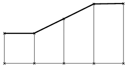
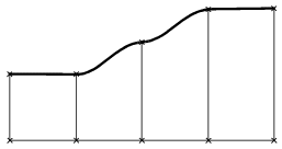
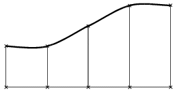
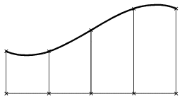
- Shape: Specifies the shape of the surface, i. e. the transition type between the individual selected profiles.
|
Linear Shape
|
Local Shape
|
Smooth Shape
|
Global Shape
|
|
| |
See Approximation tab |
| |
See Output tab |
| |
Click onto the 'More Info' button to display deviations and output results. |
 |
| |
- Display: Depending on the options selected, values are displayed in the graphics area.
- Deviation:
- Guides: Displays the maximum deviation of the Guide curves from its true mathematical position
- Profiles: Displays the maximum deviation of the Profile curves from its true mathematical position
- Support: Displays the maximum deviation of the result from the support surfaces at the surface limits defined
by the first and last Guide and Profile curves.

- U+V: Display of the UV vectors of curves and surfaces.
- Output Result: See Output Result
|
|

|
 .
.