 |
This task describes how to calculate a Head Impact analysis.
|
 |
Note:
- The Flat Region Analysis cannot be used on surface clusters with non-manifold edges (common edges of adjacent surfaces
deviating from each other, thus causing gaps or overlaps). If necessary, the surfaces must be joined using the command
Join with an appropriate tolerance.
- To be able to display the analysis, the display mode 'Shading with Material' or 'Shading with Material and Edges' must
be activated.
During execution of the Flat Region Analysis command, you can display the tesselation of the selected surface by activating
the display mode 'Wireframe'. However, the display of the analysis result is not possible in this display mode!
- The Flat Region Analysis can only be carried out temporarily and cannot be saved.
|
 |
Increased demands on the passive safety for automobiles are affecting to an increasing degree the protective properties in
potential regions of head impact at the exterior and interior of a vehicle. The Head Impact Analysis has been developed especially
for the requirements of the automobile industry. It can be used to detect sharp edges and corners at a 3D model that may cause
injuries. |
 |
| |
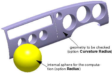
A sphere simulating a human head with a radius to be defined is used as test object. The region of the selected surface cluster
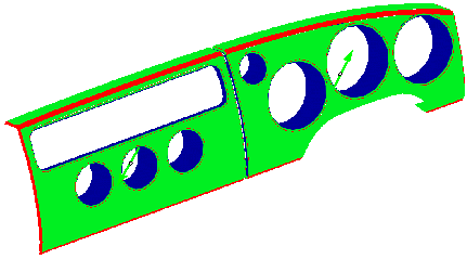
where the sphere is rolled along, will be checked for curvature radii below a minimum value. Critical zones are marked in red.
Afterwards, the detected areas should be remodelled until they meet the required safety standards. |
 |
| |
Interpretation of the analysis result
|
| |
The analysis will be displayed in the following colors:
| Color |
Meaning |
| Red |
The curvature radius is lying below the minimum, sharp edges/corners are found. |
| Green |
The curvature radius is lying above the minimum, sharp edges/corners are not found here. |
| Blue |
The sphere does not touch the geometry, no radius check is done here. |
 |
Note:
The diagnosis result can be adulterated by duplicate surfaces. In order to eliminate this source of error, use the diagnosis
Surface Checker, option Duplicate Elements. |
|
 |
Open the document HeadImpactAnalysis.CATPart. |
 |
-
Click the Head Impact Analysis icon
 . .
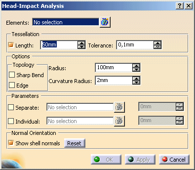
The 'Head Impact Analysis' dialog box is displayed.
|
 |
 |
You can define the following options:
- Elements:
Selection of the surface geometry to be analyzed.
|
|
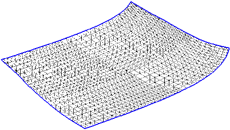
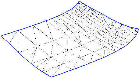
- Tessellation: The analysis is based on triangulated data. That means that surfaces are converted into a facet
model before they are checked.
- Length: Maximum length of the facets, regardless of the surface curvature.
Flat regions are identified precisely with this method, however, it requires more computing time. The smaller the value
for the facet length, the more precise, but also slower is the computation.
- Tolerance: Maximum deviation of the facet model from the surface for a curvature dependent tessellation.
The surfaces are subdivided into smaller facets until the distance of the planar facets from the surfaces is smaller
than this value. Through this, large facets are created on areas with a lower curvature, and smaller ones on surfaces
with a stronger curvature. This method delivers a quick result, but in flat regions it may lead to results that are
hard to interpret.
|
Length
Tolerance
|
| |
Options:
- Topology
- Sharp Bend: Detection of sharp bends.
- Edge: Detection of topological edges.
- Radius: Radius of the sphere. A 'standard head' has an assumed radius of 80 resp. 85 mm.
- Curvature Radius: All geometry regions with curvatures being lower than this radius will be marked as critical
in red.
|
| |
- Parameter: Optionally you can specify additional curvature radii.
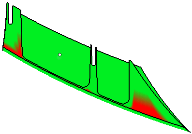
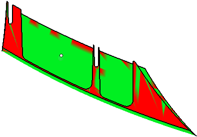
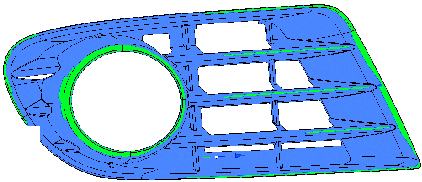
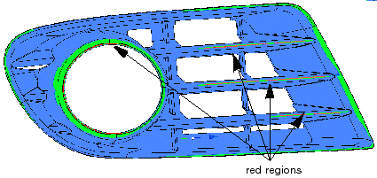
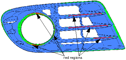
An example geometry shall illustrate these options. The following figure show diagnosis results with different curvature
radii – at first without definition of additional safety radii.
| Curvature Radius 1.0 mm – no red regions |
Curvature Radius 3.0 mm |
 |
 |
| Curvature Radius 5.0 mm |
 |
- Separate: A second curvature radius can be defined, and a surface can be selected as separating surface.
The geometry areas in the direction of the surface normal on the one hand and in opposition to this normal on the other
hand will then be checked with different radii.
The second curvature radius specified here will take effect on that side of the separating surface which is determined
by the displayed surface normal vector.
The figure below illustrates the position of the separating surface in the example geometry.
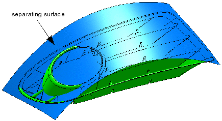
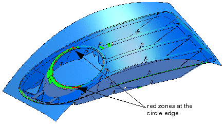
In the following figure you can see that only two independent parts have remained of the red zone of the circle edge.
The shaded display makes this particularly clear.
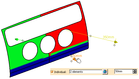
- Individual: Individual curvature radii can be defined for the diagnosis at separate patches.
 |
Note:
The number of definable radii is restricted to 99. |
You can select individual surface elements as input. On each selected element the radius is displayed numerically and
can be modified.
The text field in the dialog box displays the global default setting for each selected element.
- Normal Orientation
- Show shell normals: The normal of each shell is displayed. The normals can be inverted by clicking the middle
handle of the manipulator.
- Reset: The normal inversion can be reset.
|


 .
.


