-
Click the Curve Projection icon
 .
.
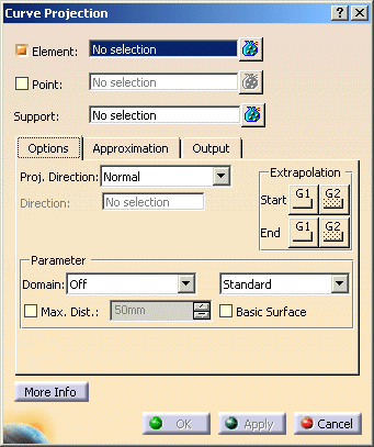
The 'Curve Projection' dialog box opens.
-
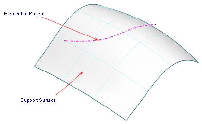
Select the curve as 'Element'.
-
F8 to move to the next selection field.
-
Select the surface as 'Support'.
-
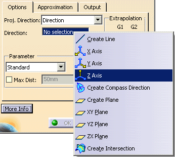
Set the 'Proj. Direction' to 'Direction'.
-
Use the context menu of the 'Direction' field to set the option 'Z Axis'.
-
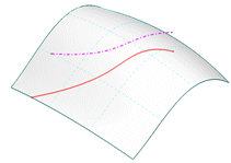
Select 'Apply'. The curve is projected on the surface.

-
Select the option 'G1' for 'Start' in the 'Extrapolation' field.
-
Select 'Apply'. The start position of the projected curve is tangentially extrapolated.

-
Select the option 'G1' for 'End' in the 'Extrapolation' field.
-
Select 'Apply'. The end position of the projected curve is now also tangentially extrapolated.

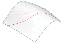
-
Select the option 'G2' for 'Start' and 'End' in the 'Extrapolation' field.
-
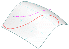
Select 'Apply'. The start and end position of the projected surface is extrapolated depending on curvature.

- Element: Selection of the curves to be projected.
- Points: Selection of projection points.
- Support: Selection of the projection support (surfaces).
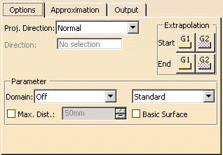
- Proj. Direction: The projection can be executed in one of the following directions:
- Normal: The projection is in the direction of the surface normal.
- View: The projection is in the current view direction.

Note: In central perspective, the projection is carried out along the view direction of the screen centre. Thus, original curve and projection curve are not congruent outside the screen centre.. - Direction: The direction can be defined via the field Direction.
- Extrapolation: These options are only available for the projection on surfaces.
Start and/or end of the projected curve is automatically extrapolated to the nearest surface edge and trimmed. The curve is extrapolated by the amount of its length at maximum .
The extrapolation types G1' or 'G2' can be defined separately for the curve start and end (see figures above). - Parameter: Parameterization of the projection curve
- Domain: The following options are available:
- Off: The parameterization of the curves to be projected is calculated across the entire curves independent of the selected support surfaces.
- Separate: The curves can either be projected onto the support as a whole, or separately onto each selected surface.
- Divide: The parameterization of the curves is calculated across the entire curve, but the result is divided at each of the support surface boundaries.
- 2D Curve: The 2D curve is a parameterized NURBS curve.
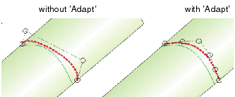
- Standard: The control point distribution of the original curve will be preserved.


Note: This setting is suitable if the curve can be projected clearly on the support, and if original and projected curve are looking largely similar. - Adapt: The parameterization of the projection curve is adapted to that of the support to realize a better
control point distribution. When using this option, the projection curve should lie nearly isoparametrically on the
support.
- Max Dist: When projecting a curve on a surface, only those points having a distance from the original curve that is smaller than the value specified here are taken for the computation.
- Basic Surface: The curves can be projected onto the underlying surface of the face selected as support.

Note: This option is recommendable when the curve to be projected is larger than the face being used as the support.
- Domain: The following options are available:
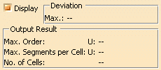
- Display: The graphical display of the deviation values can be globally switched on and off.
- Deviation
- Max: Display of the maximum deviation between projection curve and support.
- Output Result: See Output Result
![]()