Filling Surfaces

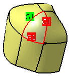
This task explains how to create a surface between a closed loop of curves.
With this function can be created a filling surface without star point from 1 to 4 one or multi-segment edge curves to be specified. You can influence the transition quality by selecting adjacent geometry as projection base and/or by adjusting the normals at the transition edges.
Open the Fill.CATPart document.
  1. Click the Fill icon:
    The Fill dialog box appears.
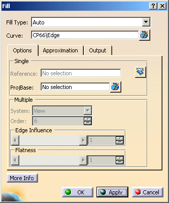


  1. Select the edges in the loop of surfaces and press Apply.
    The surfaces to fill will be created automatically.
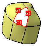
 
  1. Click OK to create the fill surface.

You can define the following options:
  • Fill Type
    • Auto: Single Patch Solution (Default option).
    • Reference: A single patch can be chosen to project it onto the selected region.
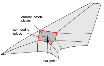
    • Multiple Surfaces: Here the star point solution will be offered.
  • Curve: Selection of curves or surface edges.
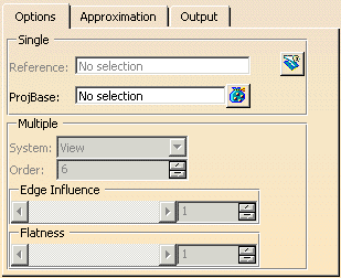
  Options tab
 
  • Single (Single patch solution):
    • Reference: An additional patch can be selected which will be projected to the boundaries already selected through Curve.
      • Trim: The created fill surface is trimmed at the boundaries.
    • ProjBase: The surfaces, curves, or edges adjacent to the filling surface can be selected as projection base. On the adjacent geometry will be computed points to which the filling surface will be approximated.
 
  • Multiple (Multiple patch solution):
    • System: After pressing Apply, there is a point in the middle of all created patches. Its movement influences all created patches. The selection adjusts the coordinate system for the movement direction of the star point:
      • View: Moving plane parallel to screen.
      • Model (Default): Moving plane parallel to XY model plane.
      • Compass Plane: Moving plane parallel to XY compass plane.
      • Compass Normal: Moving in Compass Z-Direction.
    • Order: Defines the exact order of the resulting Multiple Patch Solution.
 
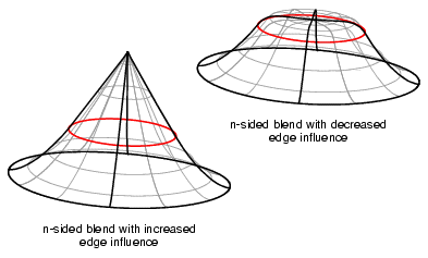
  • Edge Influence: This option controls the influence of the cross edge tangents on the patches to be created. In case of a surface created in a round gap an increased edge influence will keep the edge tangency to a larger extent.
 
  • Flatness: This option controls the influence of the tangent plane of the star point.
    High values create a large and very flat region around the star point, whereas small values create a peak.

  See Approximation tab
  See Output tab
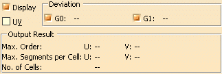
  Click onto the 'More Info' button to display deviations and output results.
 
  • Display: Depending on the options selected, values are displayed in the graphics area.
  • Deviation:
    • G0, G1: Displays the maximum continuity deviation of the resulting filling surface measured against the projection base as a result of the approximation settings imposed.
  • UV: Display of the UV vectors of curves and surfaces.
  • Output Result: See Output Result