This task shows how to create a single patch from several adjacent patches.
Open the PatchFromPatches.CATPart document.
-
Click the Patch from Patches icon
 .
.
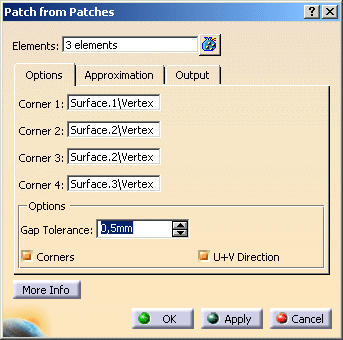
The Patch from Patches dialog box is displayed.
-
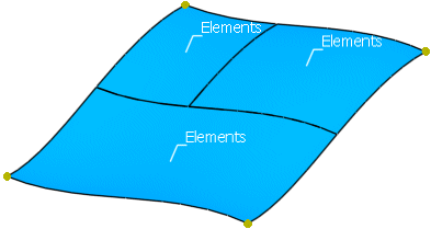
Select Surface.1 to .3
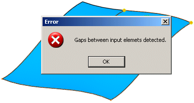
After selecting the first surface, a gap warning will appear.
Close the warning window with OK and change the Gap Tolerance to 0,5mm.
Select the third surface and terminate the selection.
The calculated corner points are now displayed.
-
Select Vertex/Surface.1 as Corner 1. The U+V Direction of the patch created is displayed.

-
Select the other corner points and click OK to create the patch.
- Elements: Selection of the elements from which a patch shall be created.
The distance between the selected elements must be within the Gap Tolerance.
Joins must have at least G0 continuity.
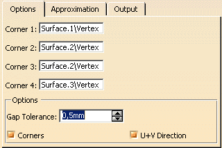
- Corner 1-4:
With these options, the four points defining the result are selected.
The system computes the topological boundary, as well as the corner points of the selected patch cluster. The calculated corner points are displayed graphically at the patch cluster. - Options:
- Gap Tolerance: The distance between the patches of the selected cluster must be within the specified tolerance. If not, a corresponding warning will be displayed and the value has to be increased to be able to calculate a result.
- Corners: Display of the corner points which can be selected for the patch creation.
- U+V Direction: Display of the U and V direction of the patch to be created.
The U and V direction is defined by the selection of Corner 1. It can be changed by selecting another corner point for Corner 1.
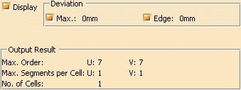
- Display: Depending on the options selected, values are displayed in the graphics area.
- Deviation:
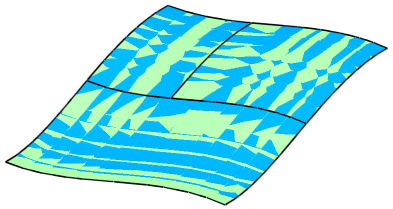
- Max. : Indicates the maximum deviation of the result from the selected elements.
- Edge: Indicates the maximum deviation of the result edges from the edges of the selected elements
- Output Result: See Output Result
![]()