This task shows how selected geometry elements can be mirrored at a symmetry plane.
- The Mirror Analysis does not create new elements, but only a mirrored image of the original geometry.
- The mirrored elements can neither be selected nor modified.
- Modifications on the original geometry will be adopted on the mirrored geometry.
- Analyses are not carried out on the mirrored geometry.
- The display of the original geometry and the mirrored geometry can be set individually using the command 'Hide/Show'.
-
Click the Mirror Analysis icon
 .
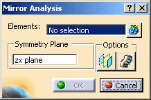
.The 'Mirror Analysis' dialog box is displayed.

-
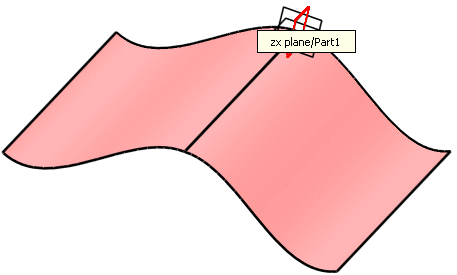
Select the element to be mirrored. After the selection the geometry mirrored at the zx plane of model coordinate system (default setting) is displayed.

-
Press F8 to change to the field 'Symmetry Plane' in the dialog box 'Mirror Analysis'.
-
Select the yz plane either via the context menu or by graphic selection. The element is now mirrored at the yz plane.

-
With the option 'Display plane' the symmetry plane can be displayed as transparent surface.

-
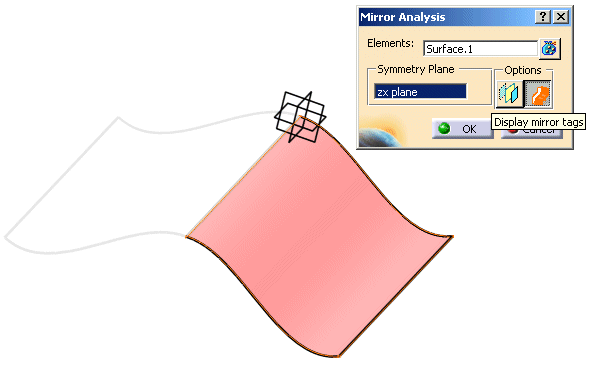
With the option 'Display mirror tags' the mirrored element is highlighted.

Note:
The color of the mirror tags can be selected with the option Feedback color in the menu Tools > Options > ICEM Shape Design > General.
