You simply activate Connect Checker while the Matching Constraints command is active.
-
Click the Matching icon
 .
.
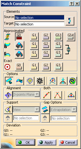
The 'Matching Constraint' dialog box opens.
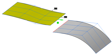
In the following example, we are going two match two surfaces.
-
Click on the Source surface near the edge you would like to match.
-
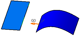
Click on the Target surface near the edge the Source surface has to snap to.
An arrow appears. Its origin marks the edge which will be matched.
-
Click Apply in the Matching dialog box to match the surfaces.
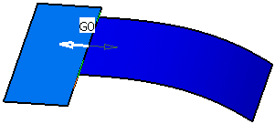
-
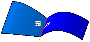
Undo the last step and click the arrow. The Target surface will now be snapped to Source surface.
Source and Target can also be inverted by the option Invert.
-
Click OK to match the surfaces.
Elements
- Source: Selection of the element to be deformed.
- Target: Selection of the target geometry.
Datum and Feature point elements are also supported as target elements for G0 continuity.  Invert: Swap Source and Target.
Approximated
 Orders of continuity:
Specifies the matching transition.
 Begin and End Edge continuities:
Aligns the cross tangents at the edges of the source and the target.
- Begin and End Edge continuities OFF: All cross tangents will be aligned coplanar only, i. e. there may be an angle between the cross tangents of the source and the target.
- Begin or End Edge continuities ON: The beginning or end cross tangent of the source will be aligned collinear to the beginning or end cross tangent of the target.
- Begin and End Edge continuities ON: All cross tangents of the source will be aligned collinear to the cross tangents of the target.
The shape of the surface can be designed by moving the second row of control points parallel to the common edge using manipulators on beginning and end points.
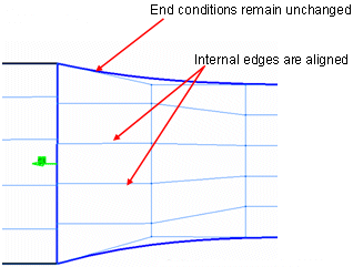
 Lock Boundaries: The end conditions of the source element can be locked while modifying internal edge conditions/control
points.
 Exact: Request is better fulfilled but Parameterization
is not kept. Check Deviation.
Options
 Partly: Allows to match the
source edge to part of the target edge.
The snap manipulator allows you to snap the vertex of the source element to a point.
Usage of the option Minimum Corner Distance in Tools > Options > ICEM Shape Design, General tab.
When the option 'Partly' is used, it is some times possible that the corners of the source surface do not coincide with the corners of the target surface. In scenarios where there are multiple surfaces whose corners converge at the same point, this can cause problems in join creation where there may be the possibility of overlapping and gaps between surface edges.
The Min Corner Distance value is only relevant available when Partly is selected.
This value would be used when the contact points of a source surface will be dragged along the edge of the target edge.
When the movement of the contact point is released or stopped, and the source surface vertex is within the corner distance tolerance value, the source surface vertex point automatically snaps to the surface vertex of the target surface, thus avoiding any small gaps between surfaces.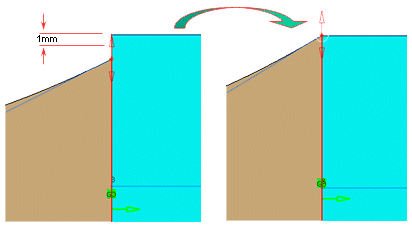
 Inside: The edge of the
source surface is projected onto the target surface. The direction depends on the option Support.
 Basic Surfaces:
Provides the ability to match a source surface to the underlying basic surface of a target surface which is represented
by a face.
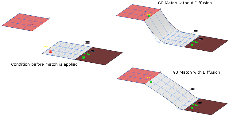
 Diffusion: The maximum number of rows
of control points is modified.
 Adapt: The order of the target edge will be
adopted from the source.
 Auto Apply: Modifications are applied automatically.
![]() Alignment:
Every control point row can be organized according to the following criteria:
Alignment:
Every control point row can be organized according to the following criteria:
- 3-points Plane: Projection orthogonal of control points on a 3 points plane. For each control point row of the surface to match, a plane is defined from the 1st, the 2nd and the last control point. All points of each row are projected into its plane.
- Mean Plane: Projection orthogonal of control points on a mean plane. For each control point row of the surface to match a mean plane is defined, and all points of each row are projected into its plane.
Both: Modify source element and target element:
 Mean: OFF: Modify source object only / ON: Modify
both objects
 Extension: Both objects meet at their extension,
instead mean point.
 Common Edge: G1, G2: Only the common edge
is modified. G3: More to come.
 Along direction: The direction for projection can
be specified via the pull-down menu (View, User line/plane).
Gap Options
 : Enables Gap matching. Does not work with Both.
- Extrapolation: Matching against an internal extrapolation of the target surface.
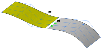
- Parallel: Creates a Matching Constraint that maintains a parallel gap to the edge of the Target element.
G1- G3 information is taken from the Target element.
- Offset fix
- Offset norm
- Extrapolation: Matching against an internal extrapolation of the target surface.

Deviation: Maximum value of deviation.
- G0: Distance - absolute.
- G1: Angle between the tangents or normals - absolute.
- G2: Radius error - relative.
- G3 (in ISD only and ISD AeroExpert): Angle (Envelope of curvature hedgehog) - absolute.