-
Click the Refit icon
 .
.
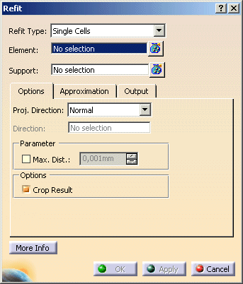
The 'Refit' dialog box opens.


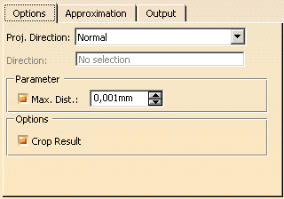
- Proj. Direction: This option is used to define the direction in which the elements shall be projected onto the
support elements.
- Normal: The normal of the support defines the projection direction.
- View: The projection direction is the Z axis of the view plane.
- Direction: An individual projection direction can be defined in the 'Direction' field.
- Parameter:
- Max. Dist.: If the check button is switched on, the Refit calculation includes only support elements with a distance to the original elements smaller than the value specified in the text field.
- Options:
- Crop Result: If the selected elements are faces (trimmed surfaces), the underlying surfaces are cropped to the size of the faces. When projecting oversize elements onto a small support, a better result will be created using this option.

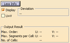
- Display: Depending on the options selected, values are displayed in the graphics area.
- Deviation: Indicates the maximum deviation of the Refit result from the support.
- U+V: Display of the UV vectors of curves and surfaces.
- Output Result: See Output Result
![]()