Associative use-edges are the use-edges, which are associative to the
geometrical inputs. If input geometry is modified, then the use-edge
becomes not up-to-date, and can be updated using the view update. To create associative use-edges, select Create
associative use-edges option, from the Tools > Options >
Mechanical Design > 2D
Layout for 3D Design,
Geometry
tab. If this option is cleared,
then non-associative use-edges are created.
The associative use-edge created on input geometry is composed of one or
several marks that define one or more connex areas of the geometry. The
marks created can be simple or complex curves. A simple mark consists of
single basic 2D element and complex mark consists of multiple 2D
elements.
Creation of associative use-edges
| Use-edge functionalities | 2D Geometries | 2D Use-edges | Vertices | Edges | Faces | Volumes | Bodies |
| Projection | Yes | No | Yes | Yes | Yes | Yes | No |
| Intersection | Yes | No | Yes | Yes | Yes | Yes | Yes |
| Silhouette | No | No | No | No | Yes | Yes | No |
When creating a use-edge from a geometrical input external to the part containing the edited 2D Layout, a geometrical import will be created in the current part. Whether this geometrical import is linked to the original geometry depends on the option Keep link with selected object, in Tools > Options > Infrastructure > Part Infrastructure, General tab.
In the Visualization toolbar, activate the
Display Backgrounds as Specified for Each View
![]() .
Go to
Tools > Options >
Mechanical Design > 2D
Layout for 3D Design,
Geometry tab and select Create
associative use-edges option. When selecting this option, associative use-edges are
created by default. You can still create non-associative use-edges, by activating
the option in the Tools Palette. If you clear the Create
associative use-edges option you can still create associative
use-edges by deactivating the option in the Tools Palette.
.
Go to
Tools > Options >
Mechanical Design > 2D
Layout for 3D Design,
Geometry tab and select Create
associative use-edges option. When selecting this option, associative use-edges are
created by default. You can still create non-associative use-edges, by activating
the option in the Tools Palette. If you clear the Create
associative use-edges option you can still create associative
use-edges by deactivating the option in the Tools Palette.

-
Double-click the front view to activate it.
-
Select the element to be projected. For the purpose of our scenario, select the half circle from the big end in the front view.
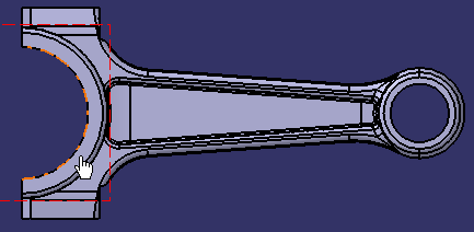
-
Click Project 3D Elements
 in the 3D Geometry toolbar (Use-Edge sub-toolbar) or select Insert > 3D
Geometry > Use Edge > Project 3D Elements from the menu bar.
A use-edge is created. It is associated to the geometry. A new node Use-edge inputs is added to the specification tree with 3D Sub-element input.1 referencing the newly created use-edge geometrical input.

- The use-edge is added in the Use Edges node under
the respective view node in the specification tree. Any new
use-edges created are added under this node. To view this
node, select the Display features under views check
box (using
Tools > Options > Mechanical Design > Drafting > General
tab, Tree area).

- Under the Use Edges node, a sub-node
indicating the use-edge creation type is given along with its
graphical representation:
-
 Project 3D Elements
 -
 Intersect 3D Elements
 -
 Project 3D Silhouette Edges.
Further in this sub-node, the use-edge created is represented as Mark:
- If the mark is made up of only one sub-element, the icon displayed in the specification tree is the representation of this sub-element. If the sub-element is a circle, the specification tree representation of the mark will be a circle and if the sub-element is a line then representation of mark is a line.
-
If the mark is made of many sub-element, the specification tree representation will be an envelope.
When the mark is composed of multiple sub-elements, selecting it in the specification tree selects all the 2D sub-elements in order to create an offset easily.
-
- The Use Edges node is created by default. To view it or not in the specification tree is your choice. Thus you can select the Display features under views option even after use-edge has been created.
- The Use Edges node is added to the specification tree when the first use-edge is created. The node is removed from the specification tree when the last use-edge is deleted.
- The main family node Use Edges is not selectable as it is used to group the use-edges created. When trying to select a family node, the selected object will be the parent view of the node.
- The contextual menu for the use-edges in the specification tree is the same as when selected in the view geometry.
- Objects created directly in the sheet are not displayed in the specification tree.
- The active sheet and view nodes are highlighted with blue background.
-
Right-click the use-edge (Mark.X object) in geometry. A contextual menu is displayed, with the following commands:
-
Isolate: isolates the associative use-edge making it non-associative with geometry
-
Deactivate: removes the associative use-edge from update process (the use-edge is still associative to geometry but is not updated)
-
Auto Search: performs an implicit profile search starting from this geometry
-
-
Right-click a use-edge sub-element input and select Parents/Children.... The Parents and Children dialog box is displayed, providing a summary of the links created to 3D.
For more details on an element, double-click it in the dialog box.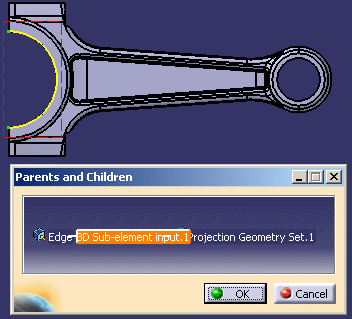
Associative use edges can be created using the Intersect 3D Elements
![]() and Project 3D Silhouette Edges
and Project 3D Silhouette Edges
![]() commands depending on the type of input you want to give.
commands depending on the type of input you want to give.
Replacing a Reference Element using the Definition Command
-
If necessary, double-click the front view to activate it.
-
In the view, select the use-edge for which you want to replace the input geometry.
-
Right-click the use-edge in geometry and select Mark.X object > Definition to edit the reference element. You can also double-click the use-edge in the geometry. The 2D Layout Use-Edge edition dialog box is displayed.

-
In the geometry, select another element to be used as input. In this case change the reference element to the circle on the small end as shown.
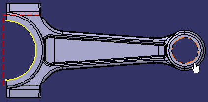
-
Click OK. The use-edge geometrical input is modified. 3D Sub-element input.2 is added to the specification tree.
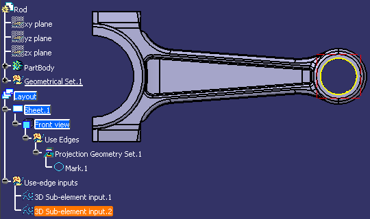
Replacing a Reference Element using the Replace Reference Geometry Command
-
If necessary, double-click the front view to activate it.
-
In the specification tree, select the use-edge input for which you want to replace the reference geometry.
- Right-click the 3D Sub-element input.1 from specification tree and select 3D Sub-element input.1 object > Replace Reference Geometry.
- In the
geometry, select
another element to be used as input for use-edge. In this case select the edge as shown.
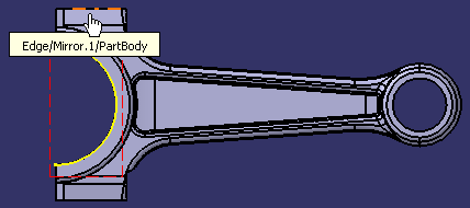
You can now notice that all use-edges created from this input, as well as layout, sheets and views containing these use-edges, turn not up-to-date. You need to update the layout so that all the changes on the use-edge inputs are taken into account.
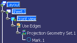
- Click
Update.
You can notice that the input geometry has been replaced.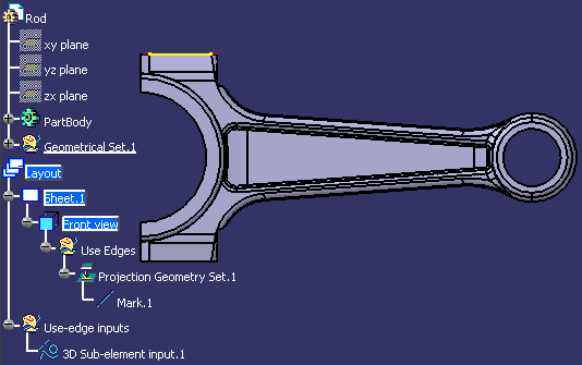
- If you
try to select an incorrect type of geometry, a
forbidden sign is displayed, along with a tooltip providing advice on the type of geometry
that you can select.

- Use-edge inputs must be of the same nature as the geometry
reference:
- 3D feature (such as Pad, Hole, Chamfer, or any object displayed in the specification tree under a part body).
- Internal/External 2D feature (geometries from a 2D Layout view). If a use-edge input has a 2D reference out of the CATPart file, then it cannot be replaced with an input, which is inside the file.
- 3D geometrical sub-element (face, vertex, edge).
- When using the Replace Reference Geometry command you modify all the associated multiple use-edges i.e. the Projection Geometry Sets.
More about Associative Use-Edges
-
Associative use-edge marks are used as other 2D curves to create dimensions, constraints or annotations. You can create dimensions for a mark or for a mark sub-element as any other 2D geometry.
-
If a mark is composed of a single element, you can create dimensions, annotations and constraints for it.
-
If a mark is composed of multiple elements, you can create only dimensions and annotations for its basic sub-elements. You cannot create dimensions for the whole mark.
-
-
Use-edges are visualized in yellow color with thickness and linetype as defined in the current curve standards, which is modifiable in the Style toolbar.
The color can be modified globally for the next created use-edges using Tools > Options > 2D Layout for 3D Design, Geometry tab, Colors field, Protected elements drop-down list.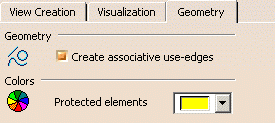
-
Use-edge cannot be copied or pasted.
-
When the input geometry of a use-edge or the plane support of the 2D Layout view changes, use-edge mark becomes not up-to-date.
When a mark is not-up-to-date, the update icon appears on the view icon in the specification tree containing this mark. You cannot update a use-edge independently of a view, which contains it.
-
If the geometry undergoes a major change (such as deleting the edge of a solid), which prevents the use-edge from being updated, then an error related to this use-edge is triggered when updating the view.
-
Use-edge can be re-routed to new specification, by editing it and selecting new geometrical input.
-
When a use-edge is deactivated, then it is not updated even if input geometry or view plane changes. Activating or deactivating a use-edge mark will activate or deactivate all marks for that use-edge.
-
When deleting a use-edge mark, the whole use-edge is deleted.
-
Use-edges, which have geometry imported from other parts as an external reference or a datum geometry, will not be deleted when the use-edges are deleted. You must delete these imports specifically, if you do not need them anymore.
-
You can isolate a use-edge using the contextual menu available on each mark. When isolating a use-edge mark, this use-edge and its marks are deleted and replaced by identical standard 2D geometries, with no link to input geometrical element.
Dimensions and annotations created on this use-edge mark are not automatically rerouted to the newly isolated geometries.
The Isolate command is also available using Insert > 3D Geometry > Use Edges > Isolate from the menu bar, as well as in the Projections/Intersections tab of the Sketch Analysis dialog box using the Sketch Analysis command. -
When creating a new part from Product Data Filtering workbench, the use-edges in the new part are isolated.
-
The Edit > Search command can be launched for associative use-edges of the following type:
-
Projection
-
Intersection
-
Silhouette
-
Mark.
-
-
List of associative use-edge inputs are displayed in specification tree after the sheets node.
-
You cannot delete use-edge inputs from the specification tree. When you delete a use-edge input, all use-edges impacted by this input will be marked as not-up-to-date. You will have to edit, deactivate, isolate or delete these use-edges.
-
If the use-edge is made up of multiple connex geometries, then associativity with the geometrical input is not kept. A message informs you when this is the case.
-
Annotation created on a sub-element mark cannot be moved to another sub-element mark.
-
Centerlines and axis lines cannot be created on use-edge sub-elements.
-
Use-edges are not created automatically when offsetting or constraining elements.
-
Mark sub-elements are not accessible when they are seen in the 2D background of a view. Thus, you cannot add a dimension on a sub-element of a 2D mark if is does not belong to the edited 2D layout.
-
Use-edges can be analyzed in the Sketch Analysis command, in the Projections/Intersections tab of Sketch Analysis dialog box. For more information refer to Analyzing View Geometries.
-
You can create a driving dimension between a simple use-edge and a geometrical element. In this case, if the use-edge is isolated, the driving dimension takes into account the geometrical element created from the isolated use-edge.
![]()