 |
The tool path of a machining operation can be modified
after it is simulated, as long as a tool path trace is displayed on the
geometric data. |
 |
To see the trace of the tool path display during
simulation, select Tool > Options > Machining Simulation > Machine
Tool Path Simulation > Simulation
tab,
and select the Display Tool Path during Simulation option.
Also, see Tool > Options > Machining Simulation > Machine Tool Path
Simulation > Simulation
tab
for information on setting the Modification Range option.
The number of segments you can modify when you select Modify Tool
Path depends on the Modification Range. |
 |
-
Simulate the entire machine operation by following the
steps outlined in Simulating NC Tool Paths,
then click Machine Simulation  . .
| The Process Simulation toolbar disappears; the tool path is displayed as shown
below: |
 |
-
Right-click on any segment of the tool path displayed
in the 3D view and select Modify Tool Path.
 |
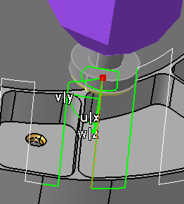
| Once Modify Tool Path is selected, the machine is
placed within the selected tool path segment, the segment is
highlighted in green, a compass is attached to the tool mount
point, |
 |
| and the Modify Tool Path dialog box is displayed. |
 |
|
Using
Save Config
When a machine configuration is saved, a
label named Configuration.X appears beside the tool
path point in the tool trace. Deleting this label will delete
the corresponding machine configuration that was associated with
this point. This label will appear during tool path based
simulation, whenever the tool path trace is ON, and the tool
reaches that particular point. |
|
|
-
Select the Lock Activity check box.
| Locking an activity is only necessary for tool path
modification. Activity editing options (Insert,
Modify, and Delete) are available only if
you have selected the Lock Activity check box. |
| Once the activity is locked, the Insert Mode and
Preview Mode areas are activated. |
-
Select the Preview check box to activate the
Insert or Modify options within the Preview
Mode.
| Use these options to see the preview of a modification without
actually inserting or modifying the tool path. To facilitate
modification, the tool axis is displayed for the current point (in
blue), the preceding point, and the succeeding point (the latter
two appear in red). Modified or inserted points are labeled as such
(see point circled in pink). |
 |
Perform the Modification
|
-
Select the Jog check box.
| You can use the Jog dialog box to
modify the tool position to create an insert point. When you
insert a new point in the tool path, (e.g., a point between Point 5
and Point 6), the new point is labeled with a number one greater
than the last point in the current path segment (e.g., if there
were 12 points in the path when the Modify Tool Path dialog box
opened, the new point is Point 13). |
-
In the Simulation area, use the Modify Tool
Path dialog box to simulate partially the tool path within the range
defined in Tools > Options > Machining Simulation > Machine Tool
Path Simulation > Simulation tab.
 |
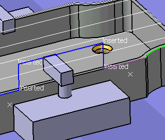
When you modify, insert, or delete any point, this is reflected
immediately in the tool path shown in the 3D view. For each
insertion and modification, a label reflects the appropriate
interaction done. |
| |
 |
| |
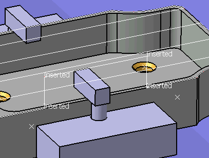
When the modifications are complete, the tool path is displayed
as shown below. |
| |
 |
-
To remove the tool path display, right-click on any
segment of the tool path displayed in the 3D view and select
Remove Tool Path Trace.
|
 |
About Modify Tool Path Options
|
|
|
A detailed listing of the
Modify Tool Path options appears below:
| Option |
Effect |
| Current Point |
Selecting a point from the Current Point
list makes the tool jump to the point on the geometry. If you
accessed the Modify Tool Path dialog box via Fault List,
among the points listed is a Collision Point. |
| Modifications area |
| |
 |
Go to start of process |
| |
 |
Go back one step. |
| |
 |
Go forward one step. |
| |
 |
Go to the end of the process |
| |
Insert Mode (this area is not available
unless the Lock Activity check box is selected) |
| |
|
Insert |
Add a point in the NC tool path
- the sequence of the point within the path (relative to the
Current Point) depends upon whether Before or
After is selected
- the location of the point is determined by the position of the
machine when Insert is selected
|
| |
|
Modify |
Modify a point's location |
| |
|
Delete |
Delete a point. |
| |
|
Before |
If this option is selected, an inserted point appears before the
Current Point. |
| |
|
After |
If this option is selected, an inserted point appears after the
Current Point. |
| |
Preview Mode (this area is not available
unless the Lock Activity check box is selected) |
| |
|
Preview |
If this check box is selected, you may see a preview of the
specified type of modification without the modification being
incorporated into the tool path. |
| |
|
Insert |
If selected, you may see a preview of this modification type
without the point being inserted into the actual tool path. To
insert the point in the actual tool path, you must select Insert
in the Insert Mode area. |
| |
|
Modify |
If selected, you may see a preview of this modification type
without the point being modified in the actual tool path. To
modify the point in the actual tool path, you must select Modify
in the Insert Mode area. |
| |
Lock Activity |
Unless this check box is selected, you cannot modify the tool
path, and the Insert Mode and Preview Mode
areas of the Modify Tool Path dialog box are unavailable. |
| Simulation area |
| |
 |
Rewind |
| |
 |
Pause |
| |
 |
Play |
| |
Step Size |
In the Step Size box, type
the value or use the arrows to change the value. This option enables
you to change the simulation rate for each step. You can make
the sub-steps:
- smaller, which makes the simulation run more slowly, or
- larger, which makes the simulation run more quickly.
|
| Jog |
Selecting this check box opens the Jog
dialog box. You can use Jog to
modify the position of the machining device. |
|


