This section explains how to extract data and perform design checks on bendable pipes and tubes.
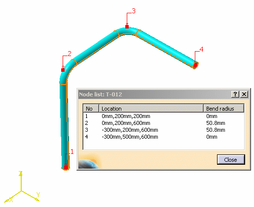
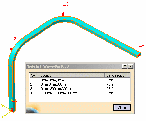
NOTE: When you place a bendable on a run, the coordinates of the bendable and the run are not always the same.
Bendables with Round and None cross sections have the same position as the run on which they are placed. Therefore, the bendable coordinates will be relative to the origin of the run. Piping Design and Tubing Design have round runs only.

Bendables with other types of cross sections are placed relative to an origin that is Point 1 of Segment 1 of the bendable. Raceway and Conduit Design and Waveguide Design have rectangular runs also.

REPORT GENERATION
The following explains results displayed when you generate a report about a bendable:
XYZ Location: The center of gravity of the bendable. The center of gravity is also defined by the X Coord, Y Coord and Z Coord columns.
Node X, Y, Z: Display the 3D absolute coordinates (relative to the root document).
Node X LocalAxisNode1, Node Y LocalAxisNode1, Node Z LocalAxisNode1: The coordinates displayed in these columns are relative to an axis defined by the bendable. The origin of the axis is Node 1 of the bendable (the coordinates displayed for Node 1 of LocalAxisNode1 will be 0,0,0,). The orientation of the axis is defined by the first segments of the bendable, where X direction is defined by the first segment of the bendable, Y direction is perpendicular to the X direction and in the direction of the second segment, and Z direction is perpendicular to the X and Y directions.