|
|
In order to calculate correctly the
parameters required for a feature (e.g., the origin of a circle, its
radius, and the normal), the feature may not always be merely selected
from the geometry. In the case of complex industrial models, some
geometry can have poor quality, especially if it originally came from
non-CATIA V5 data.
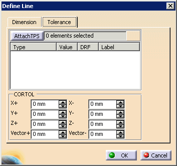
The toolboxes (see About Toolboxes) enable users to define features with the necessary degree of precision. Once these features are defined using the toolbox, however, they often need to have tolerances associated with them. |
| All of the define feature dialog boxes have Tolerance tabs (the Tolerance tab for Define Line appears below). | |
 |
|
| Composite tolerances are supported. The image below shows how the composite tolerance (highlighted in yellow) appears on a Define Cylinder dialog box. | |
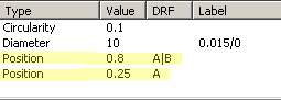 |
|
| Projected tolerances are also supported. A projected tolerance appears in the Tolerance tab of the Define dialog box with a (P) at the end of the Value column. For DMIS export, a projected tolerance zone requires the export of two bounding planes and a bound statement for the tolerance that is being exported. | |
Selecting a Tolerance |
|
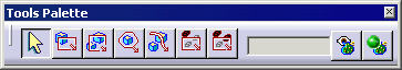
| To select a tolerance that you wish to
associate with a feature, click on the Attach TPS button.
The Tools Palette provides a variety of ways to select tolerances to associate with the feature. |
|
|
|
See About Tools Palette. |