 |
This procedure describes how to create a 321 alignment. |
 |
To create an alignment, you must have a product loaded,
and at least one feature defined and
measured. |
 |
Note that the 321 alignment does not support the idea
of thickness. |
 |
-
Select the parent process or preceding activity for
the 321 Alignment Activity.
-
On the Inspection Activities toolbar,
select the Alignment Activities toolbar, then click
321 Alignment
 . .
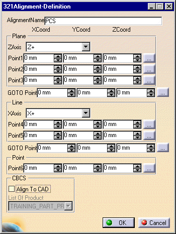
| A 321 Alignment Definition dialog box appears. |
 |
-
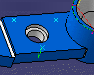
On one plane, select three points, and then a via or
goto point.
 |
| The dialog box data changes to reflect the points selected. |
-
On a perpendicular plane, pick two points, then a goto
point.
-
Select a point on a plane perpendicular to the other
two selected.
-
(Optional)
Select the Translate/Rotate to button and use the pulldown
menu to select the axis desired for alignment. The available
alignments include all V5 and V4 axes available in an assembly.
-
Click on the OK button.
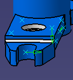
| A 321 activity appears in the process and a 321 alignment
group appears under the tag list node in the resources list.
The selected six selected points appear on the geometry as pink
dots; the two via points appear as X's. The new alignment is
represented by an x-y-z vector in thin black. |
 |
|
 |
If you create this activity before you insert a CMM
into the resource list of the PPR tree, you will be asked to confirm
that you wish to create the activity without a CMM assigned to it.
You can assign the CMM to all the
activities within the process once you are ready to insert the CMM. |
|
Once you create an alignment, it is not activated until
you use the activate alignment
command. |


