|
|
These procedures describe how to measure
features for inspection.
A feature can only be measured once. |
| When using the measure features commands,
the following information may prove helpful: The measure path can be generated when creating a feature, or it can be created using a measure feature command. The measure feature commands enable users to customize aspects of the measurement path. |
|
| Users can create an automatic or manual
measurement path. In all the measure feature dialog boxes, the
first or default tab is for automatic measurement options; the last tab
is for manual measurement options. In the image below, the select
tab on the right is the manual tab; the tab on the left is the automatic
tab.
Users can select a Probing Mode for measurement.
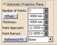
Enabling the Automatic Projection Plane option corresponds to the RMEAS feature in DMIS and enables you to create a reference measurement and to customize that measurement. The figures below show the RMEAS data and the path (in blue).
In the Distance section, selecting the Search option enables you to control how far the CMM will search for material when the CMM does not find a point (e.g., for flexible parts). All of the measure feature dialog boxes have a More button. Selecting the More button enables you to define the approach and retract planes for the secure box. For circle and slot features, you can also use operator assistance.
|


