Mapping Shapes

This task explains how to map a set of elements on a reference surface to a target surface. Geometry elements relating to a reference can be adapted to a target of the same type.

Size, shape, and orientation of reference and target are taken into account in the mapping process. If the size is different, the geometry will be scaled accordingly. If the orientation is different, the geometry will be rotated.

Open the ShapeMapping.CATPart document.
  The model contains a set of surfaces representing a logo and lying on a reference surface. The logo is to be mapped to the surface.


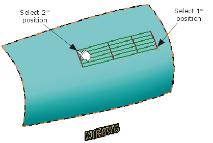
  1. Create a smaller surface (target) on the large surface with the function Creating a Surface on an Existing Surface .

 
  1. Increase the order of the target surface to 16 x 16 with the function Changing Order .

  2. Invert the surface normal of the target surface with the function Inverting Surfaces and Curves .

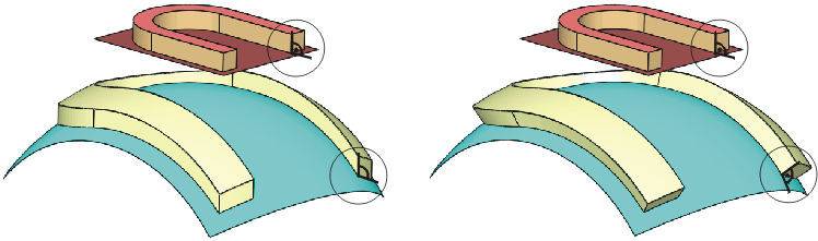
    Note: The U/V orientation of the target surface is important for the shape mapping. If the result is incorrect, you may have to invert the direction of the target surface.

 
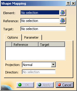
  1. Click the Shape Mapping icon: .
    The 'Shape Mapping' dialog box is displayed.


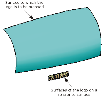
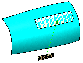
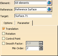
  1. Select the 68 surfaces of the Airbag logo to be mapped. (Make sure that the reference surface is not included in this selection.)
    Terminate the selection with F8.

  2. Select the reference.
    Terminate the selection with F8.

  3. Select the target.
    Terminate the selection with F8.

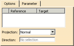
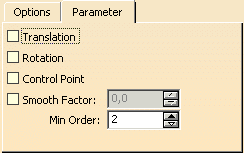
  4. Activate the option 'Translation' on the 'Parameter' tab.


  1. Click 'Apply'.
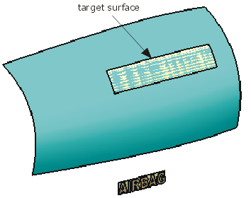
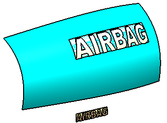
    The logo will be mapped to the target surface.

 
  1. Activate the option 'Rotation' on the 'Parameter' tab.

 
  1. Click 'Apply'.
    The logo will be rotated about the surface normal of the target surface.

Result after translation

Result after rotation

 
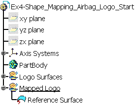
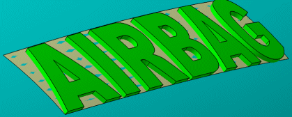
  1. The result of the shape mapping is a feature.

You can define the following options:
  • Element: Selection of the geometry elements to be mapped.
  • Reference: Selection of the reference surface.
  • Target: Selection of the target surface, on which the elements are to be mapped.
  'Options' tab
 
  • Projection: Specifies the type of projection from the geometry elements to the reference.
    • Normal: The projection is done in the direction of the surface normal in the selected point.
    • Along a Direction: The projection is done in the direction of the vector defined in the field 'Direction'.
  Parameter tab
Note:
To activate the options on this tab, you have always to click on the button 'Apply' after switching on an option.
 
  • Translation: If this option is switched on, the distance between result and target will be the same as between element and reference.
 
  • Rotation:  If this option is switched on, the angle between result and target will be the same as between element and reference.
 
  • Control Point: With this option you may define, whether the geometry or the control points of the selected geometry elements will be modified.
    • OFF: The geometry will be modified.
    • ON: The control points will be modified..
  • Smooth Factor: Smoothing for the approximation.
    • OFF: A smooth factor of 0 is used (no smoothing).
    • ON: The smooth factor can be specified.
  • Min. Order: If the selected geometry elements have a lower order than the minimum order specified here, their order will automatically be increased to this value.