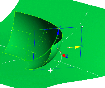
Creation of a tube surface around the spine curve.
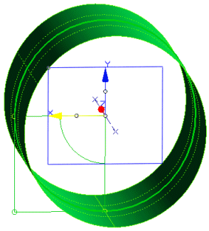
Creation of a tube surface touching the x or y axis of the local coordinate system.
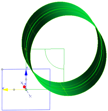
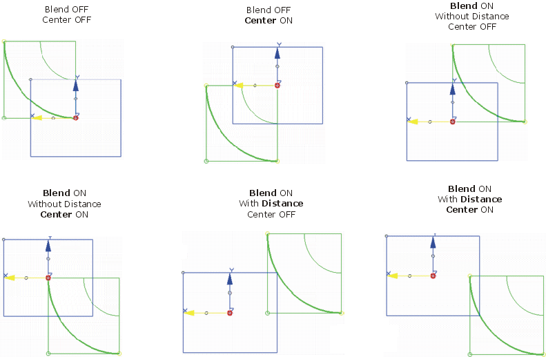
Creation of a tube surface touching the x or y axis of the local coordinate system. The surface begins in the touching point on the x axis, and ends in the touching point on the y axis.
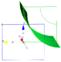
Creation of a tube surface touching the x axis of the local coordinate system, and having a distance 10 from the y axis. The surface begins in the touching point on the x axis, and ends parallel to the y axis.
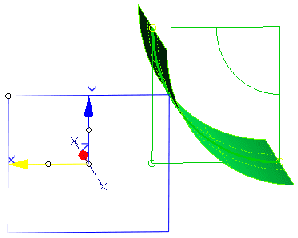
Creation of a tube surface touching the x axis of the moving frame. The surface begins in the origin on the x axis, and ends parallel to the y axis.
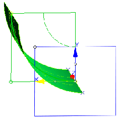
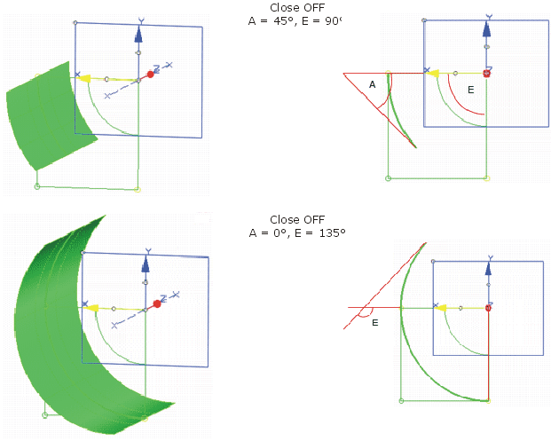
Creation of a tube surface touching the x or y axis of the moving frame. The surface begins in the touching point on the x axis, and ends when it has an angle of 135° with the y axis.
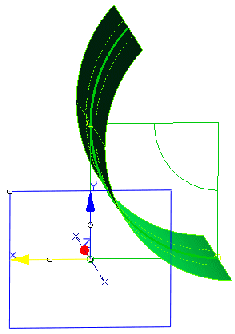
Creation of a tube surface touching the x or y axis of the moving frame. The surface begins in the touching point on the y axis, and ends when it has an angle of 135° with the x axis.
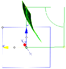
Creation of a tube surface lying on the reference surface. It begins in the projection of the spine curve in the direction of the y axis, is tangential to the reference, and ends parallel to the y axis.
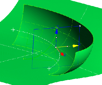
Creation of a tube surface lying on the reference surface. It is tangential to the reference, and ends at the touching point on the y axis.
-
Click the Tubing icon
 .
.
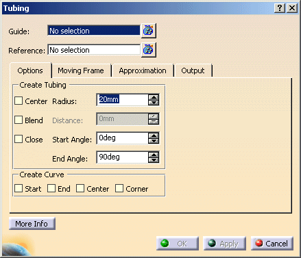
The 'Tubing' dialog box is displayed.
-
Select the curve as Guide, enter a Radius of 20mm and click Apply. A tube surface touching the x axis of the moving frame will be displayed. The surface begins in the origin on the x axis, and ends parallel to the y axis.
-
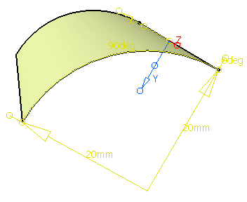
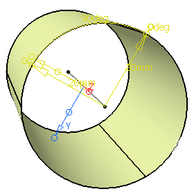
Deactivate Center, activate Blend instead and click Apply. A tube surface touching the x or y axis of the local coordinate system will be created.
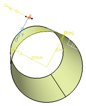
-
Deactivate Close and click Apply. Now also a tube surface touching the x or y axis of the local coordinate system. This surface begins in the touching point on the x axis, and ends in the touching point on the y axis.
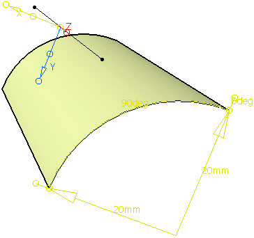
-
Enter a Distance of 10mm and click Apply. A tube surface touching the x axis of the local coordinate system and having a distance 10 from the y axis will be created. The surface begins in the touching point on the x axis, and ends parallel to the y axis.
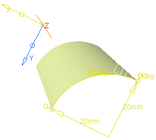
- Guide: Selection of the guide curve for the moving frame.
- Reference: Selection of a reference surface where the tube surface shall be positioned.
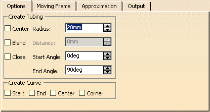
- Create Tubing
- Center: The center point of the tube surface is moved as follows relating to the origin
of the local coordinate system:
- OFF: The center point is moved along the y axis in a way that the surface touches the x axis.
- ON: The center point is lying on the x axis.
- Radius: Radius of the tube surface.
- Blend: The center point of the tube surface is moved as follows relating to the origin
of the local coordinate system:
- OFF: The center point is lying on the y axis.
- ON: The center point is moved along the x axis.
- Distance = 0: The center point is moved in a way that the surface touches the y axis.
- Distance > 0: The center point is moved in a way that the surface has the specified distance from the y axis.
- Center: The center point of the tube surface is moved as follows relating to the origin
of the local coordinate system:
Positioning the centre point with the options Centre, Blend, and Distance
- Close: An open or closed tube surface can be created.
- OFF: Creation of an open tube surface. As start and end angle, the angles between the cross tangents of the start and
end edges of the tube surface and the X axis of the local coordinate system are measured.
If a reference surface is selected, the angle is measured relative to the tangent plane of the reference surface.- Start/End Angle: Only available if 'Close' is inactive.
Defines the angle of the open tube surface.
- Start/End Angle: Only available if 'Close' is inactive.
- ON: Creation of a closed tube surface.
- OFF: Creation of an open tube surface. As start and end angle, the angles between the cross tangents of the start and
end edges of the tube surface and the X axis of the local coordinate system are measured.
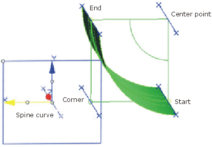
- Create Curve: Curves will be created in addition to the surface by activating these check buttons. These curves
have the shape of the guide curves and run:
- along the edge at the surface's Start
- along the edge at the surface's End
- through the surface's Center point
- through the theoretical Corner
Creation of additional curves
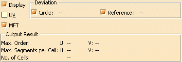
- Display: Depending on the options selected, values are displayed in the graphics area.
- Deviation
- Circle: Deviation of the approximated Bezier surface from an exact circle. Can be influenced through the segmentation.
- Reference: Deviation between the newly created tube and the reference geometry.
- UV: Display of the UV vectors of curves and surfaces.
- MFT: Display of the local coordinate system for the moving frame type.
- Output Result: See Output Result
![]()