 |
This task explains how to generate a blend surface between surface edges or curves on surfaces.
|
 |
The connecting edges may consist of several edges or curves. The transition quality between blend and connecting surfaces
may be position, tangent, curvature, or torsion continuity (G0-G3).
Additionally, curves or edges can be projected onto surfaces. In this case, the blend surface will be matched to the projected
surface curves.
The beginning or end cross tangent of the blend surface can be aligned collinear to the beginning or end cross tangent of
the adjacent surfaces.
For the blend type 'Global', the iso-curves of the blend surface can be aligned by a moving frame.
Depending on the transition quality of the adjacent surfaces between each other, the blend surfaces are matched to each other
meeting tangent or curvature continuity. The segmentation of the blend surface depends on the segmentation of the edge selected
first.
The start and end points of the connecting edges can be re-defined subsequently. Move the point manipulators at the start
and end along the selected edges (see also Context menu of the point manipulators).
|
| |
Creation of a blend surface (blend type 'Global')

|
|
In the following example, a blend surface will be created, one of the connecting edges consisting
of several elements. |
 |
Open the Blend.CATPart document. |
 |
-
Click the Blend Surface icon
 . .
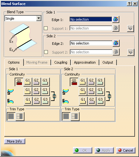
The 'Blend Surface' dialog opens.
|
|
| |
-
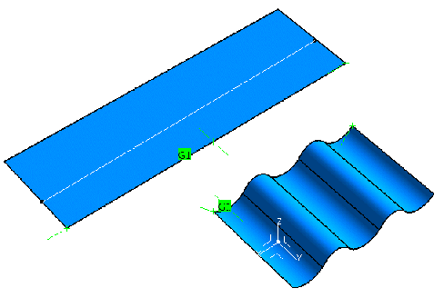
Select an edge of Surface 1 as first connecting edge ('Side 1').
Terminate the selection with F8.
-
Select edges of Surfaces 2 to 6 as second connecting edge ('Side 2').
Terminate the selection with F8.
|

 |
| |
-
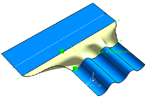
Click 'Apply'.
The blend surface will be calculated.
|
 |
| |
-
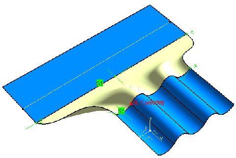
Modify the edge continuity at the start for 'Side 1' and 'Side 2' to 'G1'.
-
Click 'Apply'.
The blend surface will be re-calculated.
|

 |
| |
-
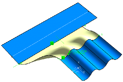
Now move the point manipulator at the start of the first connecting edge along the edge.
The connecting edge will be shortened, and the blend surface will be re-calculated accordingly.
|
 |
| |
-
Click 'OK'.
The blend surface will be created as a feature.
|
 |
You can define the following options: |
| |
- Blend type
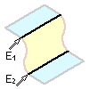 |
Single |
Creation of a blend surface with the options of the 'Options' and 'Coupling' tabs.
2nd Curve is automatically used as moving frame. |
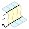 |
Global |
The 'Moving Frame' tab is additionally available for aligning the iso-curves of the blend surface.
The 'Coupling' tab is only available, if 2nd Curve is selected as moving frame
type. |
|
| |
- Side 1/Side 2:
- Edge 1: Select 1st connecting edge. By default, the edge selected first will be used as spine curve for
defining the moving frame. You can, however, select any other curve as spine curve (see 'Moving
Frame' tab).
- Edge 2: Select 2nd connecting edge.
- Support: Blend patches into the inside of a surface can be created using this option. For this, existing
curves from Edge 1 and Edge 2 are projected onto the supports in a patch normal direction to generate surface curves.
These curves are then used as the connecting edges.
|
| |
'Options' tab |
 |
| |
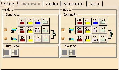
For both Side 1 and Side 2 you can define the following options:
- Continuity: Controls the transition quality between blend and adjacent surfaces for the two connecting edges.
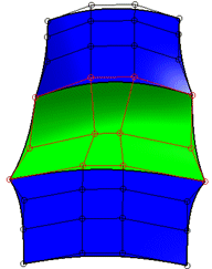
| Continuity= G0 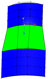
|
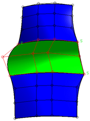
Continuity = G1 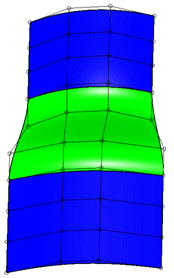
|
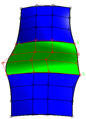
Continuity = G2 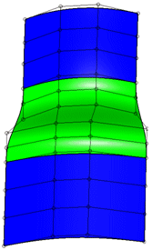
|
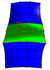
Continuity = G3 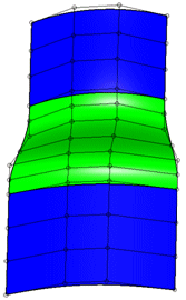
|
|
| |
 |
Edge continuity:  Aligns the beginning and
end cross tangents at the edges of the blend and adjacent surfaces. Aligns the beginning and
end cross tangents at the edges of the blend and adjacent surfaces.
- Start and End OFF: The beginning and/or end cross tangents will be aligned coplanar only, i.
e. there may be an angle between the cross tangents of the blend and adjacent surfaces.
- Start or End Edge ON: The beginning or end cross tangent of the blend surface will be aligned
collinear to the beginning or end cross tangent of the adjacent surfaces.
- Start and End ON: All cross tangents of the blend surface will be aligned collinear to the cross
tangents of the adjacent surfaces.
The following constellations are possible:
|
|
| |
- Trim Type: The underlying support surfaces can be trimmed at the connecting edges of the created blend surface.
 Creation of approximated surfaces. Creation of approximated surfaces. Creation of trimmed surfaces. Creation of trimmed surfaces.
|
| Result without trimming |
Result with trimming |
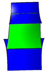 |
a) with option 
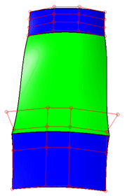
b) with option  |
|
| |
See 'Moving Frame' tab |
| |
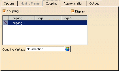
Coupling tab |
 |
| |
The Coupling function is only available in conjunction with the option 2n Curve on
the Moving Frame tab.
The Coupling function is used to influence the moving frame in order to obtain an optimal result independent from the structure
of the original geometry.
- Coupling: The coupling functionality can be switched on and off.
- OFF: If edge 1 and 2 have the same number of segments, the segmentation is decisive for the Blend Surface calculation,
i. e. the segment boundaries will be taken from the original geometry.
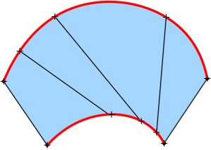
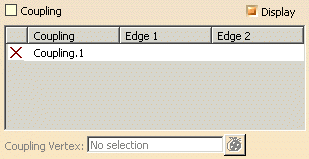
If the segmentation is unequal, the total arc length of the edges will be used for the segmentation calculation.
- ON: The segmentation is calculated according to the arc length. The arc lengths of edge 1 and 2 are determined and
on edge 2, the segment boundaries are inserted at the points whose distance value from the start and end points of edge
2 have the same ratio to the total arc length as on edge 1.
If no coupling is defined, the total arc length will be used for the segmentation calculation.
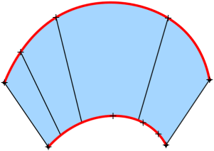
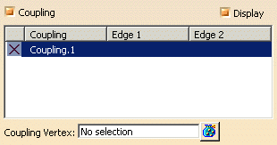
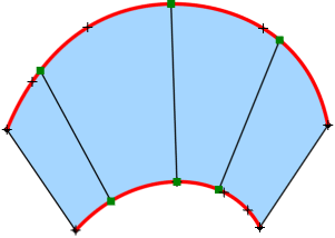
If one or several couplings are defined, for the segmentation calculation will be used the arc lengths of the sections
defined by the coupling vertices.
 |
Note: The coupling vertices can be selected arbitrarily. However, they should lie
on the edges of the original geometry and be selected in succession of their positions. |
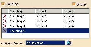
- Display: The defined couplings are displayed as lines.
- Coupling table:
- X: A defined coupling can be deleted.
- Coupling: Display of the defined couplings.
- Edge 1/2: Display of the selected coupling vertices on edge 1 and 2.
The selection can be changed after clicking onto a coupling vertex in the table.
- Coupling Vertex: For the current coupling can be either selected existing points as coupling vertex or new
points created via the context menu.
|
|
See 'Approximation' tab |
 |
| |
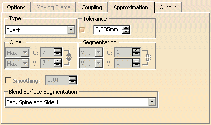
In addition to the general options for the approximation, the following options are available on
this tab:
- Blend Surface Segmentation
- Sep. Spine: The segmentation is taken from the curve selected under
Separate Spine on the 'Moving Frame' tab.
- Sep. Spine and Side 1: The segmentation is taken from the curve selected under
Separate Spine on the 'Moving Frame' tab and Side 1.
- Sep. Spine and Side 2: The segmentation is taken from the curve selected under
Separate Spine on the 'Moving Frame' tab and Side 2.
- All: The segmentation is taken from the curve selected under Separate
Spine on the 'Moving Frame' tab and Side 1 and 2.
|
| |
See 'Output' tab |
| |
Click onto the 'More Info' button to display deviations and output results. |
 |
| |
- Display: Depending on the options selected, values are displayed in the graphics area.
- Deviation (Side 1 and 2): Maximum deviation between the edges of the created surface and the connecting edges.
- Check buttons: The maximum deviation can be displayed in the graphics for each side.
- G0 - G3: Display of the maximum deviation in the dialog box.
- U+V: Display of the UV vectors of curves and surfaces.
- MFT: Display of the local coordinate system for the moving frame type.
- Output Result: See Output Result
|
| |
Context menu of the point manipulators
The context menu will be activated by clicking the right mouse button upon the point manipulators. The following options
can be defined:
 |
- Edit Relative Position: Changes the relative manipulator position.
- Keep Point: Creates the point at the picked position.
|
|
|

|

 .
.


