The command allows you to define the two types of variation to the variable radius fillet:
- Cubic
- Linear
-
Click the Variable Radius Fillet icon
 .
.
The Variable Radius Fillet Definition dialog box is displayed. Default options let you define a Cubic variation of the Variable Fillet.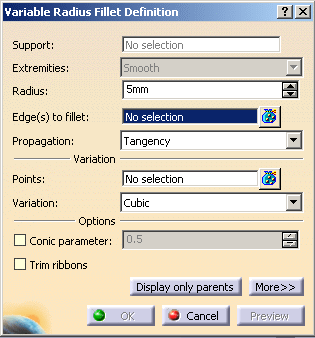
-
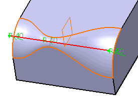
Select the edge to be filleted. You can define variable radius fillets on closed edges.
The application detects both vertices and displays two identical radius values.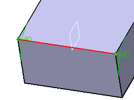
-
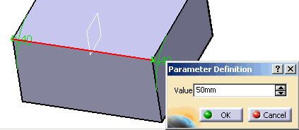
Double-click radius to access the Parameter Definition dialog box. For example, enter 50mm.
-
Click the
 icon
at the right of the
Points field. Select
Variable_Plane in the geometry.
 -
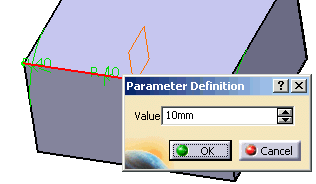
Double-click Variable_Plane radius. For example, enter 10mm.
-
Select OK in Variable Radius Fillet Definition dialog box.
For a parameter comprised between or equal to:
- 0.5, the resulting curve is a parabola.
- 0 < parameter < 0.5, the resulting curve is an arc of an ellipse.
- 0.5 < parameter < 1, the resulting curve is a hyperbola.
- Conical fillets do not handle twist configurations. If a
twist is detected, the fillet
operation fails. - Conical fillets may produce internal sharp edges due to a
curvature discontinuity of the
fillet supports. Healing is used to smooth these sharp edges. - If the
fillet surface curvature is lower than the support
curvature, fillet surface
relimitation may fail. In such cases, the conic parameter has to be decreased.
Limiting Elements
To edit this fillet, double-click EdgeFillet.1 in the specification tree. Click the More button to access the Limiting element option.
 |
![]()
- the Edges to keep option, refer to Keeping Edges.
- Circle Fillet
- Limiting element(s)
- the Blend corner(s) option, refer to Reshaping Corners.
-
Click the
 icon of
Limiting element(s) field, then select Limit_Plane in the geometry.
 -
Click this arrow to reverse the direction and therefore specify the portion of material that will be kept.
-
Click OK.
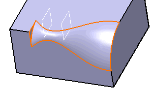
The variable radius fillet is trimmed to Limit_Plane. The final part looks like this:
 |
Variable Radius Fillet Dialog Box
Points
-
Contextual commands creating the points you need are available from the Points field:

-
Create Point: For more information, see Creating Points
-
Create Midpoint: creates the midpoint of the line you select
-
Create Endpoint: creates the endpoint of the line you select
-
Create Intersection: see Creating Intersections
-
Create Projection: see Creating Projections
-
Create Plane: see Creating Planes
If you create any of these elements, the application then displays the corresponding icon close to the Points field. Clicking this icon enables you to edit the element.
-
-
To add additional points on the edge to be filleted, you can also select planes. The application computes the intersections between these planes and the edge to determine the useful points.
-
Points can be added too by selecting 3D points.
Limiting Elements
-
It is possible to use one or more limiting elements.
-
Contextual commands creating the limiting elements you need are available from the Limiting elements field:
-
Create Point: For more information, see Creating Points
-
Create Midpoint: creates the midpoint of the line you select
-
Create Endpoint: creates the endpoint of the line you select
-
Create Plane: see Creating Planes
-
XY Plane: the XY plane of the current coordinate system origin (0,0,0) becomes the limiting element.
-
YZ Plane: the YZ plane of the current coordinate system origin (0,0,0) becomes the limiting element.
-
ZX Plane: the ZX plane of the current coordinate system origin (0,0,0) becomes the limiting element.
-
Create Intersection: Creating Intersections
-
Create Projection: see Creating Projections
-
Create Join: joins surfaces or curves. See Joining Surfaces or Curves.
-
Create Extrapol: extrapolates surface boundaries or curves. See Extrapolating Surfaces and Extrapolating Curves.
If you create any of these elements, the application then displays the corresponding icon in front of the Limiting elements field. Clicking this icon enables you to edit the element.
-
-
You can create limiting elements just by clicking on the edge to be filleted. The application displays this element as a blue disk.
-
You can select points as limiting elements. These points must be located on the edge to be filleted and they must have been created using the 'On curve' option available in the Point Definition dialog box.
