- What Are Bodies Made Of ?
- Specific Mechanisms Locate Features
- Impacts on Existing Capabilities
- Insert Added Volumes
Terminology
A Body created from V5R14 onward is still referred to as Body. Likewise, when creating a new part, the default body is referred to as Part Body.
Conversely, bodies created using application versions prior to V5R14 are no longer referred to as bodies but as Solid bodies in applications user's guides, not in specification trees.
Graphic Representations
- A Body or PartBody you create in a hybrid design environment is
identified with a green wheel icon in the specification tree:

 .
.
- Solid bodies are identified with gray icons:


However, from V5R15 onward the green icons identifying existing bodies turn yellow if you change the type of design environment to a non-hybrid design type:
|
|
For further information, refer to Graphic Representations of Bodies and Solid Bodies.
PartBody created in a Hybrid Design Environment
Solid body (here PartBody) in a Hybrid Design Environment
What Are Bodies Made Of ?
A body has only one solid result. It can contain the following entities:
- All Shape Design features
- Ordered geometrical sets (OGSs): this is possible by using the
Insert > Ordered Geometrical Sets command. For more information,
refer to
Inserting Bodies into Ordered Geometrical Sets.
Creating an OGS within a body is the same as creating an OGS within an OGS. Inserting Part Design Features in OGSs is not allowed. - Sketches
- Boolean Operations
- Solid bodies: you can integrate them into bodies thru Boolean
operations and Copy/Paste mechanisms.
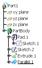
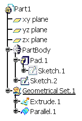
Example of a PartBody

What Bodies Do Not Contain
A body cannot contain the following:
-
Bodies
-
Geometrical Sets
-
Volumes: they cannot be created in a body but they can be created in an ordered geometrical set (OGS) contained in body. To see an example, refer to Inserting Added Volumes.
Specific Mechanisms Locate Features
Up to Version 5 release 14, bodies displayed their contents according to
two major principles: ordering and absorption. Now that they can include
additional feature types, namely surface and wireframe features, both
mechanisms apply to them too. All features in a body are displayed in the
tree so as to show a succession of steps defining the design. In other
words, the order of apparition of features in the specification tree is
consistent with the steps of creation of the design.
Unlike features within a solid body, features in a body can be set as
current: a given step of the design creation is chosen and what is located
after it is not accessible nor visible.
Impacts on Existing Capabilities
Because of new rules to be followed, a certain number of existing capabilities have been upgraded so as to reflect the changes. Here are the new behaviors you now need to be familiar with:
- Sketch Location in the Specification Tree
- Reorder
- Delete
- Surface and Wireframe Geometrical Elements Created on the Fly
- Surface-based Features
- Visualization
- Boolean Features
- Power Copies
Insert Added Volumes
The Insert Added Volumes command lets you change from the volume design to solid modeling.