 |
This section provides information regarding
the meaning of the variables set in controller profiles and robot
controller properties. |
| |
Each robot controller has profiles.
Each profile defines characteristics of different aspects of the
controller. The five profile types are:
In addition, you can access
|
|
When a robot is imported into a process
document, it automatically has a default profile for each of the five
profile types. The default profile cannot be changed. Users
can create one or more customized profiles for as many of the profile
types as they wish. For instance, one accuracy profile may be set
for a weld action; another for a via point. One tool profile should
be set for each tool mounted on the robot. Once these profiles are
created, they can be chosen for all or selected operations in a process. |
|
|
|
A tool profile is created in one of two
ways:
|
|
In the latter case, the profile takes the
name of the tool mounted on the robot. |
|
The purpose of the tool profile is to define
the physical characteristics of any tool used with the robot. The
tool's characteristics affect the robot's behavior, often subtly. The tool
profile cannot be customized as part of a move activity. |
|
The table below shows the options available in the dialog
boxes associated with
New Tool Profile
 .
The dialog boxes are: .
The dialog boxes are:
- Tool Profile (shown
before and after clicking the More button),
- Set TCP Offset (which appears after you click the Set TCP
button), and
- Set Non-RTCP Profile (which appears after you select Non RTCP).
|
|
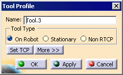
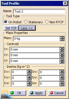
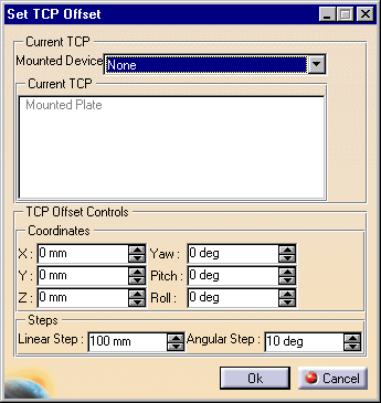
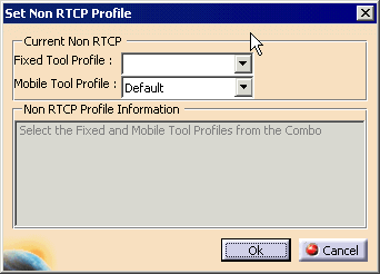
|
|
| Option |
Acceptable values |
Explanation |
|
Tool Profile |
| Name |
Text string |
The name that appears for the profile
on the PPR tree and on all menu options |
| Tool type |
On Robot Stationary
Non RTCP |
On Robot: If this
option is selected, the tool is mounted on the robot (e.g., a
weld gun).
Stationary: If this option is selected, the tool
is assumed to be external to the robot (e.g., a gantry).
Non RTCP: Users select this option to create a
non-RTCP profile, which has both fixed and mobile tool profile
capabilities. This tool profile can only be created based on the
existing list of fixed and mobile tool profiles. See
Set Non RTCP
Profile, below. |
| Set TCP |
See
Set TCP Offset, below |
| Mass** |
Numeric |
The number entered represents the mass
(in kg*) of the tool. |
| Centroid** |
Numeric |
These three coordinates (in mm*) show
the center of mass for the tool. |
| Inertia** |
Numeric |
The coordinates (in kg x mm2*)
show the rotational inertia of the tool. |
|
Set TCP
Offset |
| Mounted device |
Devices listed |
See Mounting a Device on a Robot |
| Current TCP |
Area created in the part geometry |
If multiple TCP sites are available,
one can be selected. |
| TCP Offset Controls:
|
Numeric |
Users can key in values, use the
spinners, or select a tag point on the mounting flange (if the tool
is on the robot) or a tag point on an external tool (if the tool is
stationary). |
| Steps |
Linear/Angular |
Controls the step size |
| Set Non-RTCP
Profile |
| Fixed Tool Profile |
Profiles listed |
Determines fixed tool profile |
| Mobile Tool Profile |
Profiles listed |
Determines mobile tool profile |
* These units are the default units. You can alter the units using
Tools>Options.
**This option does not apply if the tool type is stationary. |
|
|
|
A motion profile is created using
New Motion Profile  ;
see Creating and Editing a Motion Profile. ;
see Creating and Editing a Motion Profile. |
|
The purpose of the
motion profile is to specify
speed and acceleration values for the robot. One type of profile may
set speed and acceleration parameters appropriate to a particular kind of
move (e.g., moving to weld point) while another may set those parameters
in a way appropriate to a different kind of move (e.g., a via point). |
|
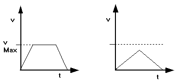
The standard velocity vs. time profile for a
move is modeled as a trapezoid, with equal magnitudes assumed for
acceleration and deceleration. If the initial and final velocities are
equal, this will result in equal acceleration and deceleration times.
Based on the distance between points and the specified TCP speed, the
velocity/time profile may end up being a triangle, i.e., the maximum speed
may never be attained (see the following diagrams). |
|
|
|
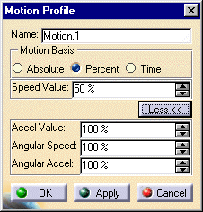
The Motion Profile dialog box (after
clicking the More button) allows users to set the following options: |
|
|
|
|
Option |
Acceptable values |
Explanation |
| Name |
Text string |
The name that appears for the profile
on the PPR tree and on all menu options |
| Motion basis |
Absolute
Percent
Time |
Absolute: Selecting absolute
means that the speed value (which must be expressed in terms of
mm/seconds) is the average speed the robot will use. Percent:
Selecting percent means that the robot will move a specified
percentage of its maximum speed.
Time: Selecting time means that the user provides a set
time for the robot motion, and the robot calculates its speed to
perform the move within that time. |
| Speed value |
Numeric |
For absolute:
- For straight line motion, this speed specifies absolute
TCP linear speed.
- For joint-interpolated motion, this value is divided by the
maximum TCP linear speed to obtain the percentage of maximum joint
speed.
For percent:
- For straight line motion, specifies percentage of maximum TCP
linear speed.
- For joint-interpolated motion, specifies percentage of maximum
joint speed.
For time: The programmed duration of the move |
| Acceleration Value* |
Percent |
- For straight line motion, the percentage of the maximum TCP
linear acceleration
- For joint-interpolated motion, the percentage of the maximum
joint acceleration
|
| Angular speed* |
Percent |
For straight line motion, the
percentage of the maximum TCP rotational speed |
| Angular Acceleration* |
Percent |
For straight line motion, the
percentage of the maximum TCP rotational acceleration |
* Cannot be set when the motion basis equals time. |
|
|
|
An accuracy profile is created using
New Accuracy Profile
 ;
see Creating and Editing an Accuracy Profile. The purpose of the
accuracy profile is to
define the accuracy of a desired trajectory. ;
see Creating and Editing an Accuracy Profile. The purpose of the
accuracy profile is to
define the accuracy of a desired trajectory. |
|
When corner rounding is desired, users can
select between two different algorithms to effect it. |
|
When Speed is the selected
Accuracy Type
or mode, the
severity of the corner rounding effect is a function of the deceleration
time. In the case of straight-line motion, if the accuracy value is set to
100%, then motion to the next point begins at the start of the
deceleration profile, i.e., the robot does not decelerate. This produces
the maximum radius for corner rounding. If the Accuracy Value is set to
50%, then motion to the next point begins when half of the
deceleration time has elapsed, i.e., the robot will decelerates for half of
the time required to come to a complete halt, and then it starts the
next motion statement. If the accuracy value is set to 0%, then the move
uses the standard acceleration/deceleration profile. |
|
When the Distance is the selected
Accuracy
Type, the Accuracy Value defines the radius of a virtual sphere, centered
at the position to which the TCP is being moved. The corner-rounding
motion begins when the robot's TCP reaches any point on this virtual
sphere. Therefore, when the value of distance is non-zero, the robot's TCP
will never reach the programmed position. |
|
|
|
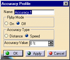
The Accuracy Profile dialog box allows users to set the following options: |
|
|
|
|
Option |
Acceptable values |
Explanation |
| Name |
Text string |
The name that appears for the profile
on the PPR tree and on all menu options |
| Flyby Mode |
On
|
Selecting On
means that the robot moves near, but does not stop at, a specific
target (i.e., there is no deceleration; the target is a via point).
|
| Off |
Selecting Off means the
robot stops at the point, i.e., |
| Accuracy Type |
Distance
|
Distance: As it moves near its
target, the robot moves within a "virtual" sphere that has the
target point as its center.
|
| Speed |
Speed: The speed represents the extent to which the robot
decelerates as it rounds the corner. A speed of 0% enables the
robot to move exactly to the target point; a speed of 100% means the
amount of corner rounding is very large. |
| Accuracy Value |
For Distance
: Radius of the target's surrounding
sphere
|
Accuracy Value
represents the radius of the sphere.
|
| For Speed: Percentage of deceleration |
Accuracy Value is a percentage of the deceleration speed at which
corner rounding should begin. |
|
|
|
| |
An object or reference frame profile is
created using
New
Object Profile  ;
see Creating and Editing and Object
Profile. ;
see Creating and Editing and Object
Profile. |
| |
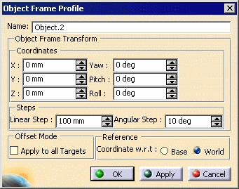
This profile is used to
define a frame, which is
used as the base of the robot. The inverse kinematics are solved
using this offset from the robot base. |
| |
The coordinate definitions can be linear or
Cartesian. |
| |
If you select the Apply to all
Targets check box in the Offset Mode area, the offset is
calculated for both Cartesian and joint (tag) targets. Otherwise,
the offset is only calculated for the Cartesian targets. |
| |
In the Reference area, the
Coordinates can be set with respect to (w.r.t.)
either the Base or the World. |
| |
 |
|
|
|
|
|
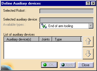
Data about auxiliary devices is added to the robot
controller using
Define Auxiliary device  ;
see Defining Auxiliary Devices. ;
see Defining Auxiliary Devices. |
|
The purpose of adding the auxiliary
devices to the robot controller is to account for their effects on the
robot movement. |
|
The Define Auxiliary devices dialog box
allows users to set the following options: |
|
|
|
|
Option |
Acceptable values |
Explanation |
| Robot |
Robot in the .CATProcess file |
The robot can be selected from the PPR
tree or the geometry. |
| Selected auxiliary device |
Device in the .CATProcess file |
The device can be selected from the PPR
tree or the geometry. |
| Available types: |
End of arm tooling
Rail/Track/Gantry |
Selected from Available types
list. |
|
| |
Robot Controller Properties
|
| |
|
| |
|
 ;
see Creating and Editing a Tool Profile.


